ESP8266 DAQ
This is a project to create a Wi-Fi enabled data collection unit supporting an 8-channel 12-bit ADC (MAX11629), DHT-11/22 temperature/humidity sensor, MQ-135 air quality sensor, supports 2 CPU fan or servo outputs, as well as a single SPI and UART interface, and is expandable to support a LiPo battery with on-board charging circuit. This project is based around an ESP-12E module, utilizing the ESP8266 Wi-Fi SOC which performs all Wi-Fi protocol processing and contains a general purpose MCU compatible with the Arduino IDE.
List of Features
- LED indicators
- Re-programmable and rechargable via micro-USB (FT-232RL IC)
- Support for LiPo battery with internal charging circuit
Electronics

Microcontroller and LCD
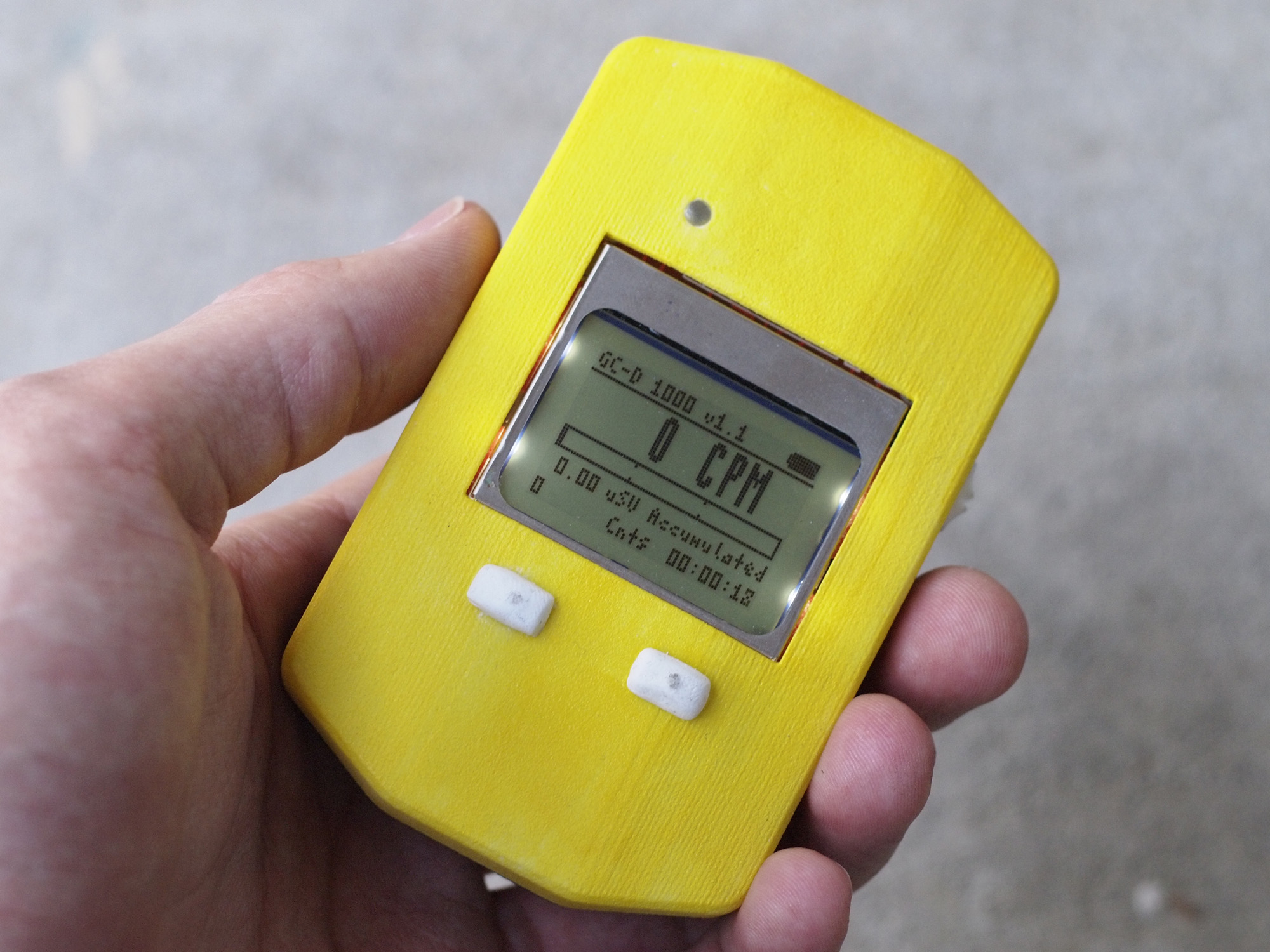
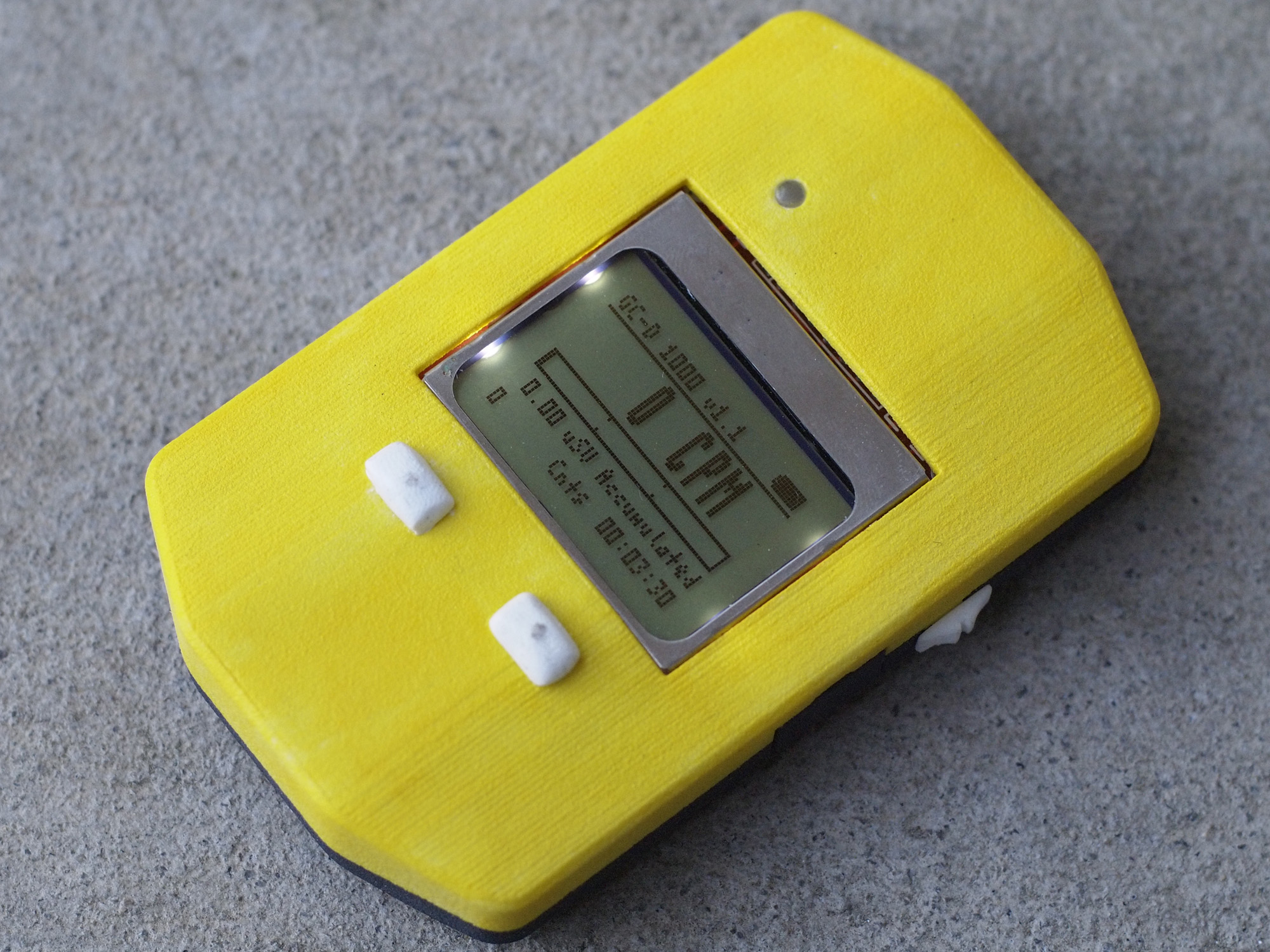
In the simplest case, a digital Geiger counter would need only two functions, to count the pulses from the Geiger tube and calculate a rate, and to display the rate on the LCD. This project simply adds a few extra features, all very simple to implement. First, the microcontroller needs to be able to count pulses from the Geiger tube over a certain time period. This is accomplished by running a timer divided down from a 24 MHz crystal. Pulses are detected by the microcontroller's hardware via a falling edge interrupt, which increments the ticks variable. The timer module produces an interrupt 50 times a second. Every second the microcontroller records how many pulses were detected since the last interrupt, and this value is added to an array of 32 values each 0.3s, which are averaged and displayed. Next, the microcontroller needs to display values and text to the screen. This is achieved by sending binary data over an SPI data interface. An LCD function library handles the low-level conversion between ASCII characters from strings or numbers in variables to characters to be displayed to the LCD. The microcontroller reads battery voltage and displays it as an 8-level bar graph. The microcontroller also optionally displays conversions in uSv/H and mR/H, and displays the corresponding accumulated dose (uSv in CPM mode). The microcontroller also maps the CPM value to a logarithmic bar graph, which is displayed in the middle of the screen.
Hardware Revisions
Revision 1.0
This is the first revision of the GC-D 1000.
PCB:
- Geiger tube signal routed to input pin with edge triggered interrupt
- USB port moved lower to accomodate enclosure design
- Voltage sense pin tied directly to VBAT allowing voltage read when switched off but plugged in (charging)
Added auto power-off capability (MCU signal to boost EN line)Removed, battery monitor should be sufficient.- Added LiPo battery monitor circuit
Enclosure:
- Added space at top of enclosure for second SI3BG size (short/wide vs. thin/long)
- Increased clearance along edge seal for better fit
- Increased tolerances for better fit of PCB and edge snaps
- Modified magnet holders
- Improved buttons to add reach and fit in holes
- Increased hole size for PUR button access (USB program button)
- Minor cosmetic/structural improvements
Outstanding Issues:
- The buttons are currently not manufacturable by Shapeways. They must be redesigned (a rectangular slot/profile would be a better approach) to have increased wall thickness.
PCB Files
Here is the Eagle schematic file for the ESP8266 DAQ: http://rev0.net/files/.sch Here is the Eagle board file for the ESP8266 DAQ: http://rev0.net/files/.brd
Enclosure
The enclosure for the GC-D 1000 was created with Autodesk Inventor 3D CAD software, and is 3D printed (in this case using a Makerbot Replicator 2). The enclosure is made of 5 separate pieces, which are assembled by snapping them together.
Here are the Autodesk Inventor files for the GC-D 1000: http://rev0proto.com/files/GC-D_1000_Model.zip
Code
Full source code for the project can be found here: http://rev0proto.com/files/gc-d_1000.zip
Photos
...
...


Total Project Cost
| Component | Cost | Source |
| ESP-12E Module | $3.33 | eBay |
| PCB | $1.40 | DirtyPCBs |
| FT-232-RL | $4.50 | Mouser |
| MAX11629 | $3.93 | Mouser |
| AP1117 | $0.27 | Mouser |
| Passives/Misc. Components | $0.25 | Digi-Key |
| Total Price | ~$13.68 |