ESP8266 DAQ
This is a project to create a Wi-Fi enabled data collection unit supporting an 8-channel 12-bit ADC (MAX11629), DHT-11/22 temperature/humidity sensor, MQ-135 air quality sensor, 2 CPU fan or servo outputs, SPI and UART interfaces, and is expandable to support a LiPo battery with on-board charging circuit. This project is based around an ESP-12E module, utilizing the ESP8266 Wi-Fi SOC which performs all Wi-Fi protocol processing and contains a general purpose MCU compatible with the Arduino IDE.
List of Features
- 802.11b/g/n Wi-Fi
- 32-bit 80 MHz RISC CPU
- 512kB(?) Flash for program/data storage
- ~38kB Free SRAM
- Uses Arduino IDE
- On-board FT232RL for reprogramming and UART comms
- micro USB connector for power/communication
- 8 channel 12-bit ADC with RC input filter on each channel
- Support for DHT-11/DHT-22 and MQ-135 for environmental sensing (temperature/humidity/air quality)
- LED indicators
- Support for LiPo battery with internal charging circuit
Electronics
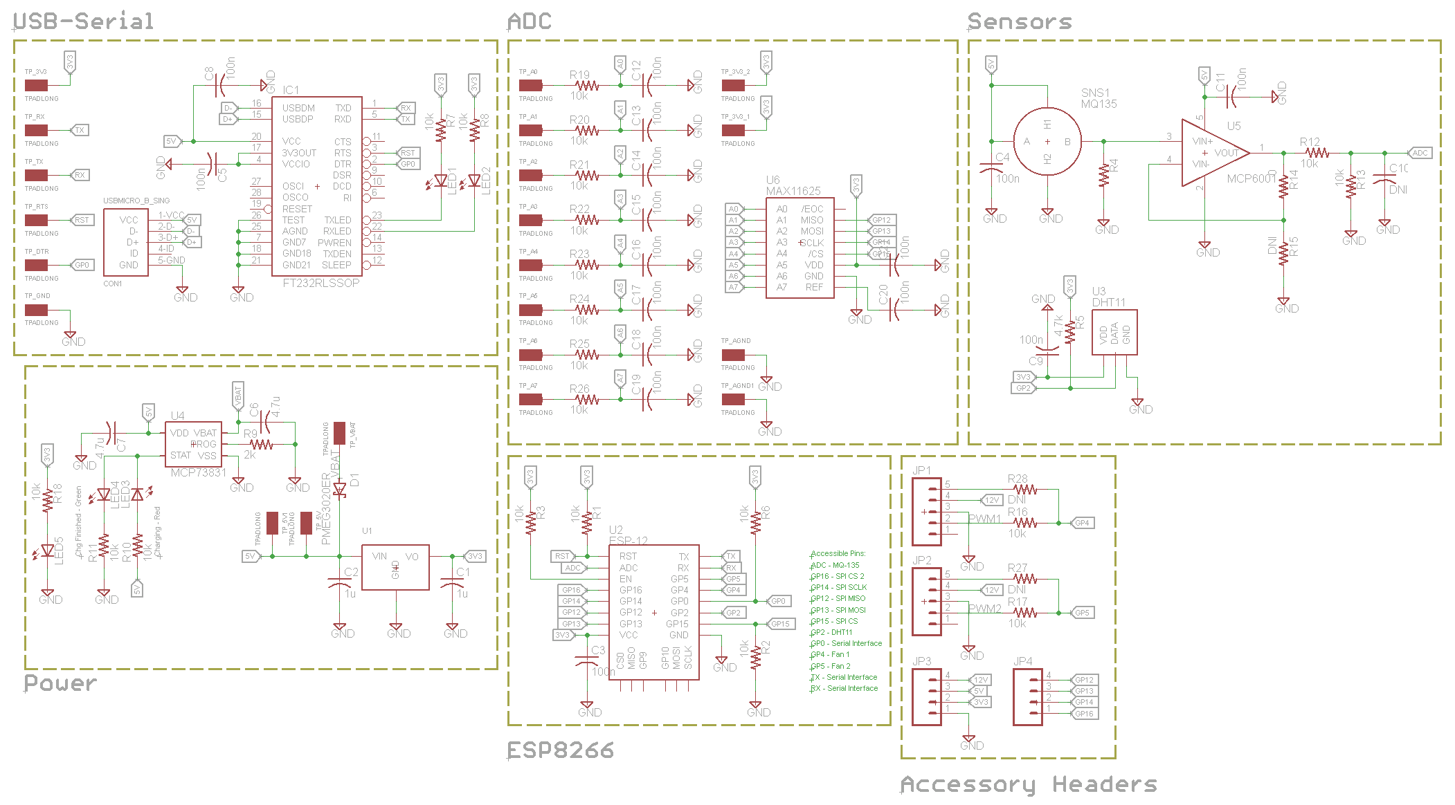

This board contains the necessary circuitry to re-program the ESP8266 with the Arduino bootloader and program/debug through the Arduino IDE. The board also adds environmental sensing capability (temperature and humidity via the DHT-11 or DHT-22 sensor and air quality/CO2 via an MQ-135) and an 8-channel ADC. The GPIOs are mapped as follows:
- TOUT (ADC) - MQ135
- TX - Serial Interface
- RX - Serial Interface
- GPIO0 - Bootloader Dedicated
- GPIO2 - DHT-11/22
- GPIO4 - Fan/Servo 1
- GPIO5 - Fan/Servo 2
- GPIO12 - SPI MISO
- GPIO13 - SPI MOSI
- GPIO14 - SPI SCLK
- GPIO15 - SPI CS (ADC)
- GPIO16 - SPI CS2 (External SPI device)
Hardware Revisions
Revision 1.0
This is the first revision of the ESP8266 DAQ.
Outstanding Issues:
- None yet!
PCB Files
Here is the Eagle schematic file for the ESP8266 DAQ: http://rev0.net/files/wifi_ws_v10.sch
Here is the Eagle board file for the ESP8266 DAQ: http://rev0.net/files/wifi_ws_v10.brd
Enclosure
The enclosure for the ESP8266 DAQ was created with Autodesk Inventor 3D CAD software, and is 3D printed (in this case using a Makerbot Replicator 2). The enclosure is made of 2 separate pieces, which are assembled by snapping them together.
Here are the Autodesk Inventor files for the enclosure: http://rev0proto.com/files/ESP8266_Enclosure.zip
Code
Basic project template for connecting to Wi-Fi access point (SSID and WPA2 key hard-coded) and posting temperature/humidity + single ADC channel to a Thingspeak channel: http://rev0proto.com/files/ESP8266_DAQ.ino
Photos
- ESP8266 DAQ Top.jpg
...