SNA DBridge

This page describes the Directional Bridge for the rev0SNA 50-2500 MHz Scalar Network Analyzer.
Summary


The Directional Bridge is based around a wideband balun and precision RF resistors. Two baluns chosen for evaulation, the Mini-Circuits TCM1-43X+, which features an amplitude balance of <0.5dB and phase balance of <7 degrees across the 50-2500 MHz operating range, and the Coilcraft JA-4220, which features an insertion loss of <2dB across the 50-2500 MHz operating range, a phase balance of <3 degrees and amplitude balance of <0.5 dB across the 50-3000 MHz range. The bridge resistors chosen are Vishay FC0402E50R0BTBST1 0402 flip chip precision 50 ohm 10 GHz RF resistors. The layout was done to minimize distances and match distances between the resistors in the bridge. The performance will largely be limited by the assembly of the RF transformer and quality with regard to phase and amplitude balance.

Testing showed both directional bridges have basic return loss functionality, however the performance of the two are both poor at the high frequency, with both showing approximately +/- 5 dB error with a -10 dB return loss load at the upper end of the frequency range, with a cumulative error of approximately 2.1 dB for both JA4220 and TCM1-43X with the -10 dB load, and approximately 3.3 dB for the antenna load. The JA4220 shows slightly improved performance at the middle of the range (~400-2200 MHz), and will be used for future projects requiring a wideband balun.
Testing
- 12.x.2013: The PCB was assembled and tested for basic functionality by measuring coupled power with and without a load attached.
- 1.28.2016: A JA4220 PCB was assembled and tested, however the PCB component was drawn incorrectly and thus the board did not function as expected. The original TCM1-43X PCB can be used for JA4220 and will be assembled and tested instead.
- 2.1.2016: A JA4220 was assembled onto a TCM1-43X PCB after discovering the error mentioned above, and both TCM1-43X and JA4220 version directional bridges were tested on a VNA from 0.1-8 GHz using a 50 ohm load, open (as baseline calibration), and multi-band antenna.

Revisions
- 1.0: Initial revision using JA-4220 balun.
- 1.1: Second revision using TCM1-43X+ balun.
Bill of Materials (v1.0)
| Part | Quantity | Unit Cost | Total Cost | Source |
| JA4220 | 1 | $4.04 | $4.04 | Coilcraft |
| (or) TCM1-43X | 1 (MOQ 20) | $3.19 | $3.19 | Mini-Circuits |
| 50 Ohm Precision RF Resistor | 3 | $2.39 | $7.17 | Digi-Key |
| SMA Female Connector | 3/5 | $2.51 | $1.51 | Dealextreme |
| PCB | 0.794"x0.538"/3 | $10.00 | $1.42 | Osh Park |
| Total Unit Cost | $14.14 |
Gallery
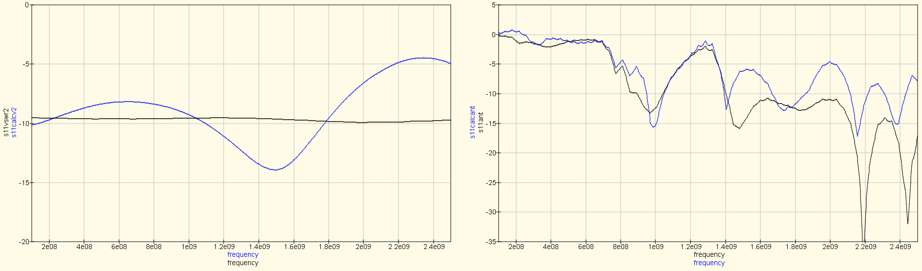
JA4220 calculated S11 response for antenna and -10 dB return loss load

References
- ↑ Mini-Circuits, "Balun Transformers". Available: https://www.minicircuits.com/pages/BalunApplicationNote.htm