Rev0Trac
This is a project to create an APRS Tracker to transmit GPS coordinates and other information over a ham radio via the AX.25 protocol.
Summary
APRS (Automatic Packet Reporting System) is a type of packet, or digital, radio protocol that enables users to transmit data such as position, weather, messages, and other information over a network of radios and repeaters called digipeaters. This allows users to tune in to the APRS frequency and within several minutes, know the locations of all stations within an area. This information can also be uploaded to the internet through systems called IGates. A short presentation on this project was given at the Cal Poly Amateur Radio Club's March 3rd general meeting, and can be found here: http://prezi.com/27z5ktni6jle/aprs-talk/
How does APRS work?
At the highest level, APRS is a packet radio protocol, meaning all data is formatted in packets following a defined standard, with each packet encoding information such as destination addresses, source address (your callsign), and error checking, along with the intended data.

First, let's define some packet fields.
- Flag: 0x7E = 0b01111110
- This field marks the beginning and end of the packet, and is not found anywhere else in the packet (this will be explained later)
- Can also fill the space between two consecutive packets
- Destination Address: Ex. 0x82, 0xA0, 0xA4, 0xA6, 0x40, 0x40, 0xE0 (APRS -0)
- This field is the destination address; who you intend to send this data to, in this case, APRS -0, a standard APRS calling destination
- The SSID of this field defines what digipeater path the packet should take, in this case the VIA path, defined below in the Digipeater Addresses field
- Note all bytes in this field (except the last) are standard ASCII character codes shifted left by 1, i.e., their hex value is multiplied by 2
- The last byte of this field follows the SSID byte format of 0bCRRSSID0, where C is the command/response bit (1 in this case), RR is 11, SSID is the SSID value, and 0 is appended to the end. This gives us: 0b11100000, or 0xE0
- Source Address: Ex. 0x96, 0x94, 0x6C, 0x96, 0xA6, 0xA8, 0xE2 (KJ6KST-1)
- This field is the source address; who is sending the packet, in this case, KJ6KST-1. A user may have up to 16 (-0 to -15) different APRS stations on the air, each with different SSID's[2]
- Again, all bytes in this field are shifted left by 1
- The last byte follows the SSID byte format listed above
- Digipeater Addresses: Ex. 0xAE, 0x92, 0x88, 0x8A, 0x62, 0x40, 0x63 (WIDE1-1)
- This field defines a list of digipeater addresses (call signs) or a generic path for the packet to follow, in this case WIDE1-1, meaning it will be repeated in 1 "hop", each digipeater decrementing the SSID until it reaches -0, meaning the first digipeater(s) to hear this packet will retransmit once for other stations/IGates to hear
- The last address in this field should end with an LSB of 1, in this case 0x65 (0b01100101), to indicate the end of the address fields
- Control Field: 0x03 = 0b00000011
- This field defines the packet as a UI (unnumbered information) frame, the default for APRS
- Protocol ID: 0xF0 = 0b11110000
- This field defines no layer 3 (network layer) implementation, again the default for APRS
- Information Field: Ex. 0x21, 0x30, 0x30, 0x30, 0x30, 0x2E, 0x30, 0x30, 0x4E, 0x2F, 0x30, 0x30, 0x30, 0x30, 0x30, 0x2E, 0x30, 0x30, 0x57, 0x3E (!0000.00N/00000.00W>)
- This field contains the information you want to send, following one of 10 main types of data, including a custom format. Here we are sending a basic GPS position report, following the format above, starting with the "!" character, and ending with a ">" character
- The information field can be followed by a comment field directly after the data, including any characters except "|" and "~"
- Frame Check Sequence: Ex. 0x38, 0x76
- This field contains a CRC (Cyclic Redundancy Check) of all data in the packet excluding the flags and FCS itself
- The CRC follows the 16-bit CRC-CCITT format, with a polynomial of 0x8408, explained in detail in the APRS Encoder section below
- The FCS is send low-byte first
- Flag: 0x7E = 0b01111110
- The end of the packet is marked by another flag
How is an APRS packet sent?
APRS uses the modulation scheme of the Bell 202 modem, called AFSK (Audio Frequency-Shift Keying), at a data rate of 1200 baud (bits per second). This uses two audio tones of different frequencies to represent binary bits, with a 1200Hz tone as the "mark", or "1" bit, and a 2200Hz tone as the "space" or "0" bit. However, if data were simply sent using this method, there are certain strings of data that would create an unintentional flag (0b01111110), and may trick the receiver into thinking the packet has ended. To combat this problem, a scheme called bit stuffing is used. Any time a sequence of 5 or more consecutive "1"s are found in the data, a "0" is inserted, ensuring that no flags (sequence of 6 ones) are found anywhere but the beginning and end of a packet. Additionally, to assist with decoding of the packet, a scheme called NRZI (Non-Return to Zero Inverted) is applied to the data. This encodes a "0" as a change in state (i.e. from a "0" to a "1" or a "1" to a "0") and a "1" as no change in state. Together with bit stuffing, this ensures that at least every 5 bits, there is a change in state to aid in clock recovery. Note that unlike bit stuffing, NRZI is applied to the flags as well. Lastly, all bytes are sent LSB (least significant bit) first.
Hardware
Specifications
- 10mA Idle, 16mA TX (without GPS)
- Typ. 65mA with GPS
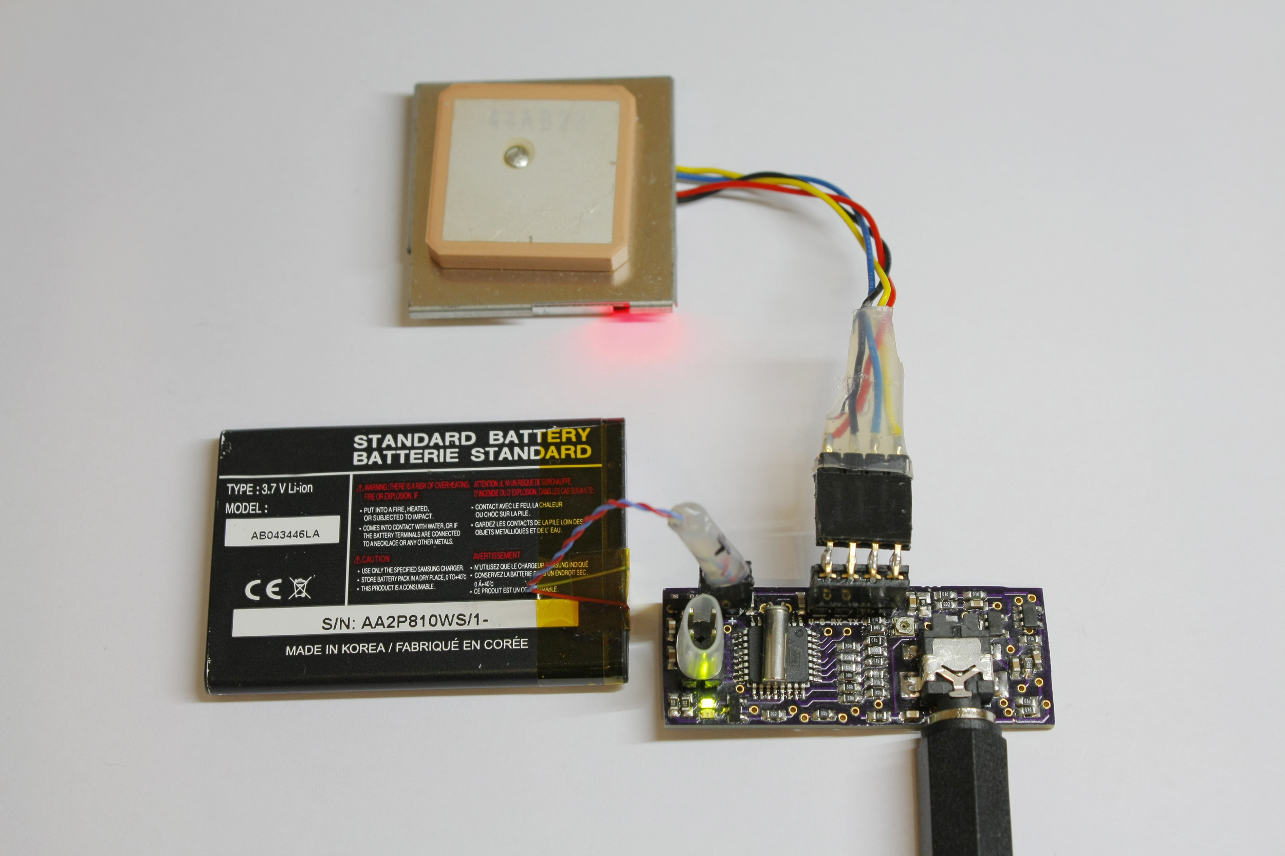
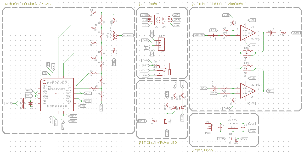
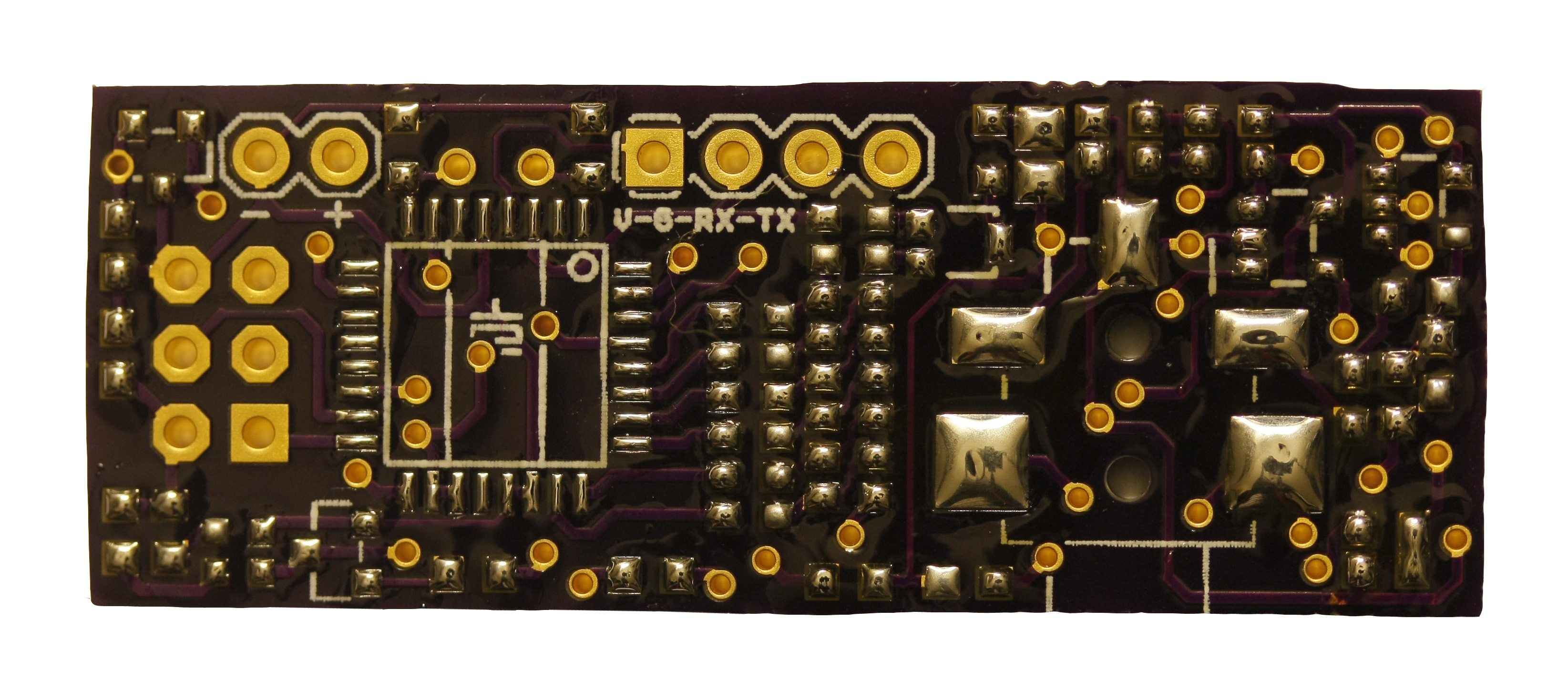
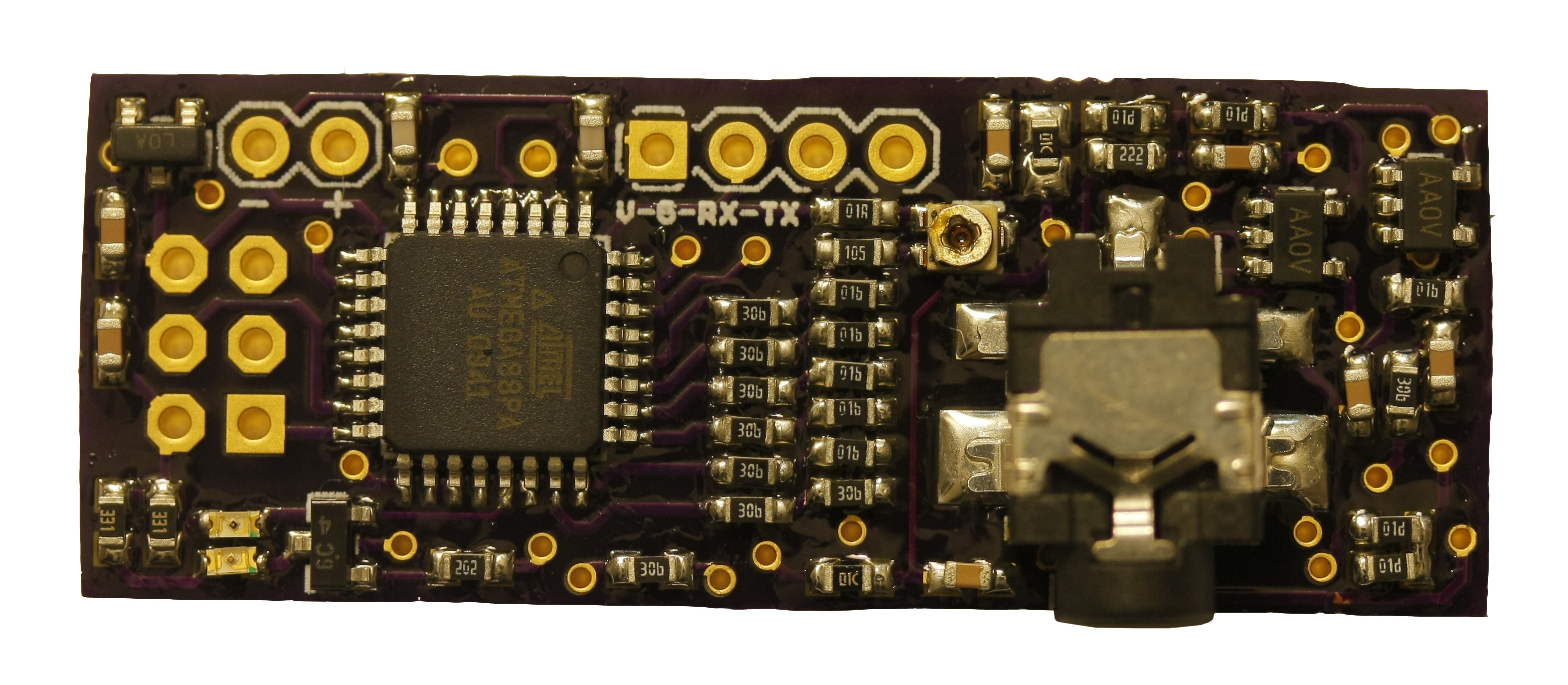
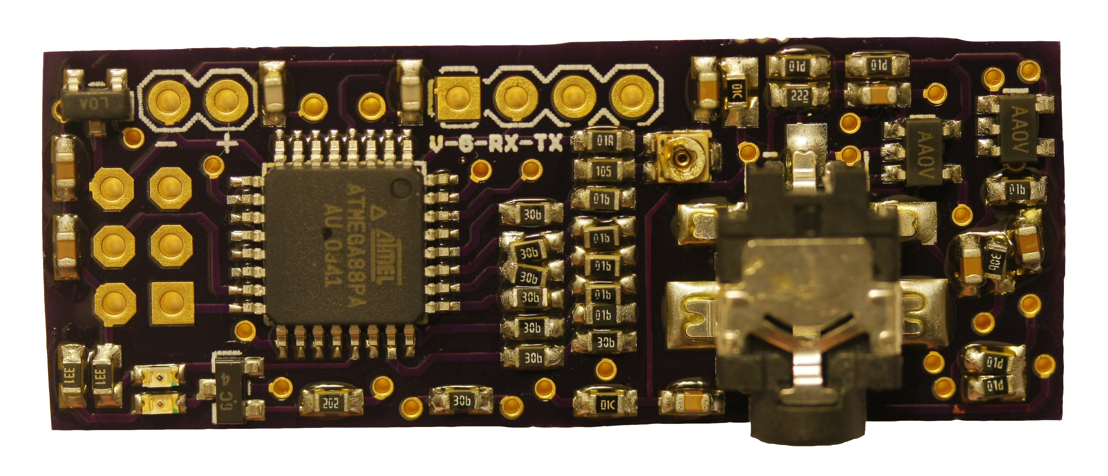
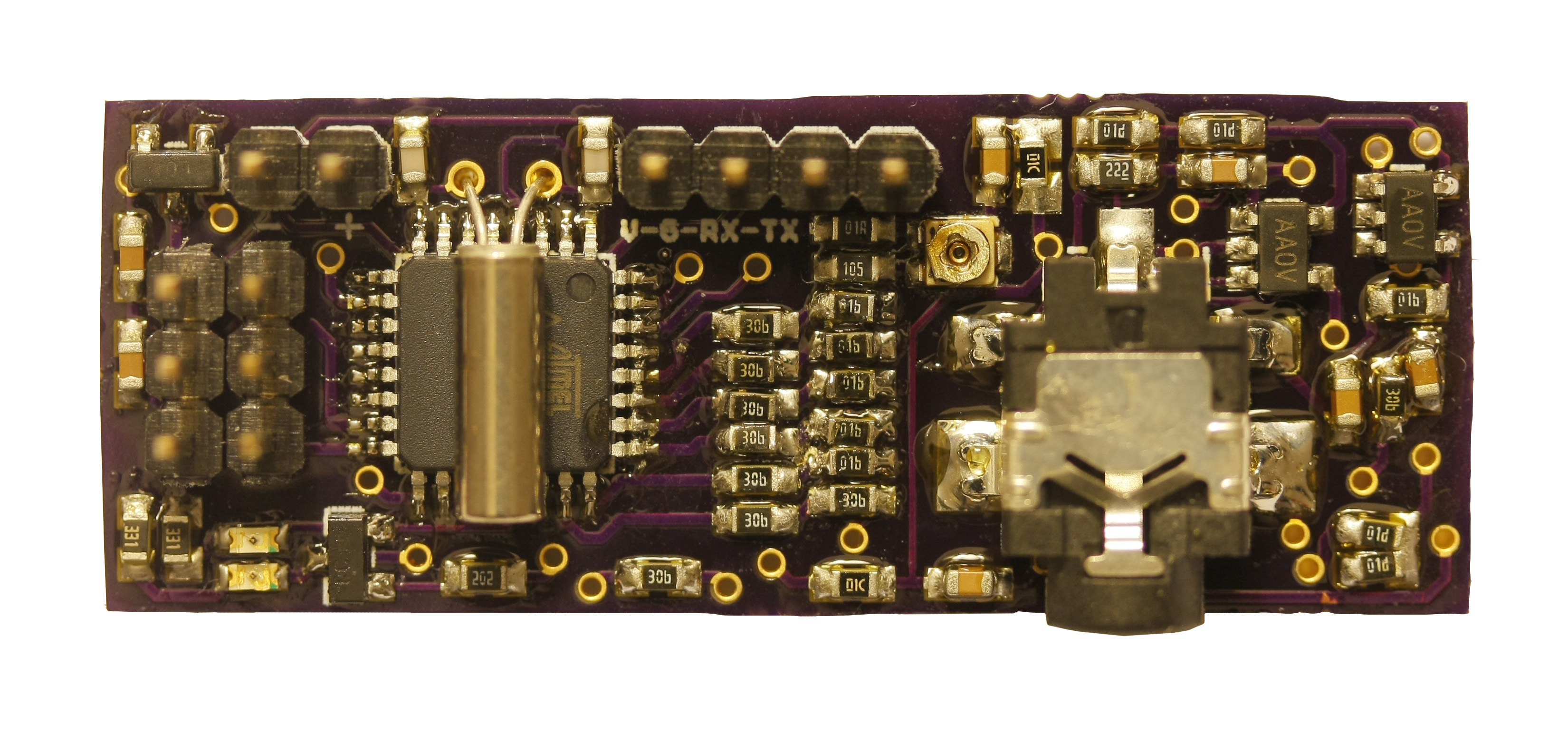
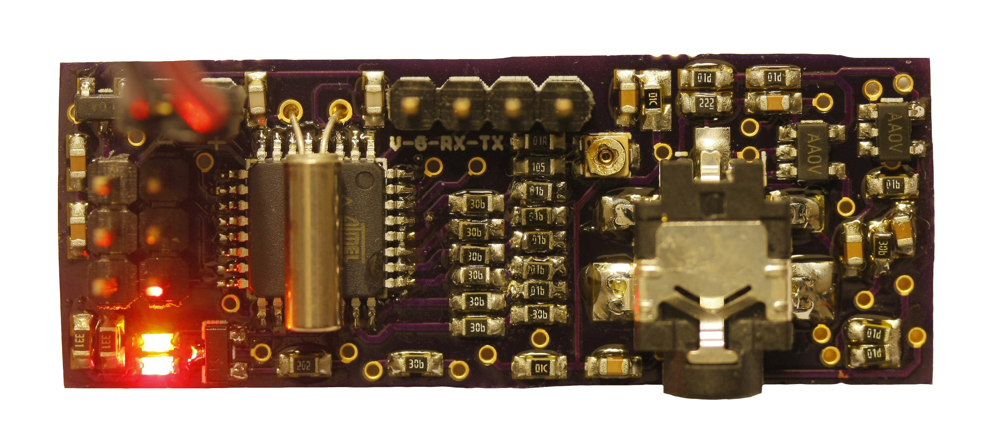
Rev0Trac is based primarily on an ATmega88PA microcontroller, chosen for ease of implementation based on the prototype (based on an ATtiny44A) and my experience with AVR microcontrollers, the USART for interfacing to a NMEA compliant GPS, and the 8kB of code space to allow for future additions to the project. The ATmega88PA generates audio tones via a 6-bit R-2R ladder, which is attenuated through 2 fixed resistors (which set the upper and lower output voltage limits) and an SMD trim potentiometer. This signal is then low-pass filtered and buffered through an MCP6001 op-amp, and output through a DC-blocking capacitor and 2.2k ohm resistor.
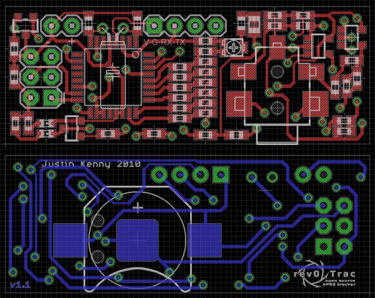
The ATmega88PA interfaces directly with a GPS module via its built in USART module and a 4-pin header on the top side of the board. It receives NMEA strings and parses the data out of the GGA sentence to update outgoing APRS packets with.
Audio is received, amplified, and low-pass filtered, and sent to the analog comparator module of the ATmega88PA. Audio levels on the input are centered about 1/2 Vcc, and can be compared to any of 32 voltages, including 1/2Vcc, Vcc, GND, Vcc + 1/32Vcc, etc., by assigning the topmost R-2R DAC pin as an analog input, selecting it as the comparator negative input, and generating a voltage with the 5 remaining R-2R DAC pins. Using this method, tones can be detected by counting the time between zero crossings of the input waveform.
Power to the unit is provided by either a CR1220 3V battery (this will only be used for testing/demonstration) or through a 2-pin header. Input voltage can range from 4.5-24V, and is regulated to 3.3V by an LM3480.
Bill of Materials
| IC's | Quantity | Unit Cost | Total Cost | Source | Part Number |
| ATmega88PA Microcontroller | 1 | $3.57 | $3.57 | Digi-Key | ATMEGA88PA-AU-ND |
| MCP6001 Op-Amp | 2 | $0.29 | $0.58 | Digi-Key | MCP6001T-I/OTCT-ND |
| LM3480 3.3V Voltage Regulator | 1 | $1.10 | $1.10 | Digi-Key | LM3480IM3-3.3CT-ND |
| Discrete Semiconductors | Quantity | Unit Cost | Total Cost | Source | Part Number |
| BC817 NPN Bipolar Transistor | 1 | $0.33 | $0.33 | Digi-Key | 568-1631-1-ND |
| Passives - Capacitors | Quantity | Unit Cost | Total Cost | Source | Part Number |
| 0.47uF 0603 Ceramic Capacitor | 3 | (Qty. 10) $0.055 | $0.55 | Digi-Key | 445-1320-1-ND |
| 0.1uF 0603 Ceramic Capacitor | 3 | (Qty. 10) $0.02 | $0.20 | Digi-Key | 445-1316-1-ND |
| 3.3nF 0603 Ceramic Capacitor | 1 | (Qty. 10) $0.024 | $0.24 | Digi-Key | 445-5084-1-ND |
| 20pF 0603 Ceramic Capacitor | 2 | (Qty. 10) $0.036 | $0.36 | Digi-Key | 445-5052-1-ND |
| Passives - Resistors | Quantity | Unit Cost | Total Cost | Source | Part Number |
| 2k 0603 1% Resistor | 9 | (Qty. 10) $0.025 | $0.25 | Digi-Key | RMCF0603FT2K00CT-ND |
| 2.2k 0603 Resistor | 2 | $0.04 | $0.08 | Digi-Key | RMCF0603FT2K20CT-ND |
| 1k 0603 1% Resistor | 6 | (Qty. 10) $0.025 | $0.25 | Digi-Key | RMCF0603FT1K00CT-ND |
| 10k 0603 1% Resistor | 2 | (Qty. 10) $0.04 | $0.08 | Digi-Key | RMCF0603FT10K0CT-ND |
| 100k 0603 1% Resistor | 4 | $0.04 | $0.16 | Digi-Key | RMCF0603FT100KCT-ND |
| 1M 0603 Resistor | 1 | $0.02 | $0.02 | Digi-Key | RMCF0603JT1M00CT-ND |
| 100R 0603 Resistor | 1 | $0.02 | $0.02 | Digi-Key | RMCF0603JT100RCT-ND |
| 330R 0603 Resistor | 2 | $0.02 | $0.04 | Digi-Key | RMCF0603JT330RCT-ND |
| Other | Quantity | Unit Cost | Total Cost | Source | Part Number |
| 4 Connector 2.5mm Audio Jack | 1 | $0.96 | $0.96 | Digi-Key | CP1-42534SJCT-ND |
| 9.8304MHz Crystal | 1 | $0.63 | $0.63 | Digi-Key | 300-8425-ND |
| 16 Pin 0.100" Male Header | 1 | $0.87 | $0.87 | Digi-Key | WM6416-ND |
| 10k Single Turn 2mm SMD Potentiometer | 1 | (Qty. 5) $0.152 | $0.76 | Digi-Key | 490-2032-1-ND |
| Misc. | Quantity | Unit Cost | Total Cost | Source | Part Number |
| Shipping | 1 | $5.49 | $5.49 | Digi-Key | N/A |
| PCB | 1.187 in2 | (Qty. 3) $5.00 | $5.94 | Laen/Dorkbot PDX PCB Order | N/A |
| Total Price | ~$22.48 |
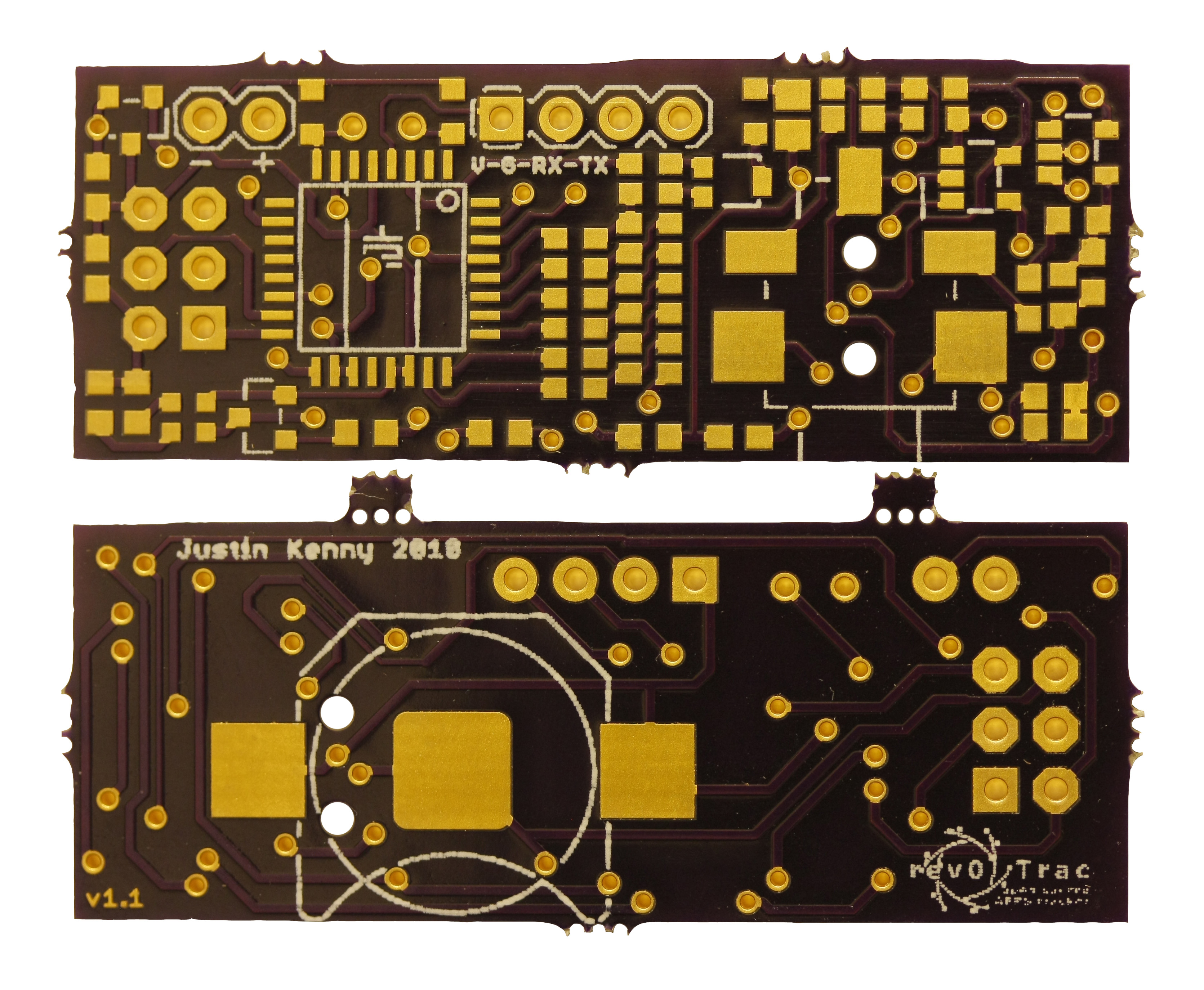
PCB/Construction Photos
<HTML5video type="youtube" width="400" height="300" autoplay="false">xyyP9Wg2PfM</HTML5video>
Software
The program can be broken down into two main components: GPS/NMEA parser and APRS encoder.
NMEA Parser
The following code runs every time a serial byte is received by the USART module:
//In main.c
ISR(USART_RX_vect)
{
   byteRX = USART_Receive();

   if(byteRX == '$') //$ = Start of NMEA Sentence
   {
      gpsindex = 0;
      done = 0;
   }
   else if(byteRX == 0x0D) //<CR> = End of Transmission
   {
      done = 1;

      if(gpsdata[4] == 'G') //Make sure this is a GGA sentence
      {
         parse_nmea();
      }
   }
   if(done != 1)
   {
      gpsdata[gpsindex] = byteRX;
      gpsindex++;
   }
}
First, the byte is read in from the receive register. If the byte is a '$', it marks the beginning of a NMEA sentence, so the index of the gpsdata[] array is set to 0. If the byte is a carriage return (0x0D), then it marks the end of the NMEA sentence, so the done flag is set high to stop accepting data into the array. The fourth byte of the gpsdata[] array is checked, if it is a 'G', it must be a "$GPGGA" sentence, so the parse_nmea() function is called. Otherwise, bytes are filled into the gpsdata[] array.
The following code parses the relevant data out of the "$GPGGA" sentence held in the gpsdata[] array:
//In gps.c
void parse_nmea(void)
{
   int i = 0, n;

   for(n=0;n<MAXCOMMAS;n++) //Find the positions of all commas in the NMEA sentence, put positions in commas[]
   {
      for(;gpsdata[i]!=0x2C;i++); //Find next comma; continue stepping through the array until we find 0x2C (,)
      commas[n] = i; //Store the index in commas[] array
      i++;
   }

   if(gpsdata[commas[5]+1] != 0x30) //Make sure we have GPS fix; 0 = invalid
   {
      for(i=commas[1]+1;i<commas[2];i++)
      {
         lat[i-(commas[1]+1)] = gpsdata[i]; //Load latitude into lat[] array from stored NMEA string
      }
      ns = gpsdata[commas[2]+1];

      for(i=commas[3]+1;i<commas[4];i++)
      {
         lng[i-(commas[3]+1)] = gpsdata[i]; //Load longitude into lng[] array from stored NMEA string
      }
      ew = gpsdata[commas[4]+1];

      for(i=commas[0]+1;i<commas[1];i++)
      {
         time[i-(commas[0]+1)] = gpsdata[i]; //Load time into time[] array from stored NMEA string
      }
      valid = 1;

      update_packet(); //Update the packet with new good GPS data
   }
   else //Else update the timestamp, but retain old GPS data
   {
      for(i=commas[0]+1;i<commas[1];i++)
      {
         time[i-(commas[0]+1)] = gpsdata[i];
      }
      valid = 0;

      update_packet();
   }
}
This function begins by storing the positions of all commas in the NMEA sentence, which separate values in a standard order. From this information, the function then separates out the latitude, longitude, E/W and N/S statuses, and the time. If the GPS has a valid lock (noted in one of the data fields), the APRS packet is updated with the new location and time. Otherwise, only the timestamp is updated, with an 'I' following the timestamp to indicate a lack of GPS lock.
The following code updates the APRS packet with GPS data:
//In gps.c
void update_packet(void) //This function updates the APRS packet with GPS information
{
   int i;

   for(i=LATSTART;i<NSSTART;i++)
   {
      data[i] = lat[i-LATSTART]; //Copy latitude into packet at position LATSTART
   }
   data[i] = ns;
   for(i=LONGSTART;i<EWSTART;i++)
   {
      data[i] = lng[i-LONGSTART]; //Copy longitude into packet at position LONGSTART
   }
   data[i] = ew;
   for(i=CMTSTART;i<(TIMEEND+1);i++)
   {
      data[i] = time[i-CMTSTART]; //Copy time into packet at position CMTSTART
   }
   if(valid) //If GPS coordinates are valid, put a V after the timestamp
   {
      data[(TIMEEND+1)] = 'V';
   }
   else //Else put an I after the timestamp
   {
      data[(TIMEEND+1)] = 'I';
   }

   if(delay == DELAYTIME) //If DELAYTIME seconds have passed, begin packet transmission
   {
      start();
      delay = 1;
   }
   else //Else continue counting up
   {
      delay++;
   }
}
The appropriate sections of the APRS data[] array are updated with the latitude, longitude, E/W, N/S, and timestamp data, as well as a flag that indicates valid GPS lock. If DELAYTIME cycles of this function call have passed, then the APRS packet is transmitted.
APRS Encoder
The following functions are used to return a single bit from the packet, start the transmission, and end the transmission, respectively:
char data_bit(char byte, char bit)
{
   return ((data[(int)byte]>>bit) & 0x01);
}
void start(void)
{
   UCSR0B = 0x00; //Disable USART Receiver, disable receive interrupt
   sbi(PORTB,PTT);
   _delay_ms(D_KEY);
   fcs = 0xFFFF;
   mark = data_bit(0,0);
   bitindex = 1;
   TCCR0B = 0b00000010; //Timer on
}

void end(void)
{
   TCCR0B = 0b00000000; //Timer off
   PORTC = 32; //Output low
   byteindex = 0;
   ended = 0;
   n = 0;
   counter = 0;
   _delay_ms(D_UNKEY);
   cbi(PORTB,PTT);
   UCSR0B = (1<<RXEN0)|(1<<RXCIE0); //Enable USART Receiver, enable receive interrupt
}
The following code updates the frame check sequence bytes after every bit is transmitted:
void fcs_update(void)
{
   unsigned char shiftbit = 0x0001 & fcs; //Store bit rotated off in variable shiftbit
   fcs = fcs >> 1; //Shift fcs right by 1
   if(shiftbit != data_bit(byteindex,bitindex)) //If shiftbit doesn't match the data being sent, xor with 0x8408
   {
      fcs ^= 0x8408;
   }
}
APRS uses the AX.25 protocol, which specifies that the end of the packet is occupied by a 16-bit frame check sequence, generated according to the CRC-CCITT format, with a polynomial of 0x8408. The CRC algorithm first begins with a 16-bit word of 0xFFFF. For each bit between the end of the first bit of the destination address and the last bit of the information field, the function shifts the CRC word right, and compares the bit shifted off with the bit being sent. If the bit being sent does not match the bit that was shifted, then the CRC word is XORed with the polynomial, 0x8408. When the FCS is sent, the word is inverted (XORed with 0xFFFF) and sent low-byte first.
The following code is run 33*1200 times per second, and is responsible for the actual transmitting of bits and the handling of the low-level packet protocol:
ISR(TIMER0_COMPA_vect)
{
   if(mark == 1)
   {
      PORTC = coslow[n];   //Output next sample of a 1200Hz cosine
   }
   else
   {
      PORTC = coshigh[n];  //Output next sample of a 2200Hz cosine
   }

   counter++;
   n++;

   if(mark == 0)
   {
      if(n>32)
         n = 15;
   }
   else
   {
      if(n>32)
         n = 0;
   }

   if((ended == 1) && (counter > 32))
   {
      end();
   }

   if(counter > 32)
   {
      counter = 0;
      //Change next sent tone according to NRZI (non-return to zero inverted)
      if((data_bit(byteindex,bitindex) == 0))
      {
         onecount = 1;
         mark ^= 0x01; //If the next bit is zero, toggle the output, else no change

         n--;
         if(mark == 0)
         {
            n += phslh[n]; //Last value was 1, add phase shift for 1200Hz to 2200Hz
            if(n>32)
               n = 14;  //If 2200Hz index overflows, start at position 15
         }
         else
         {
            n += phshl[n]; //Last value was 0, add phase shift for 2200Hz to 1200Hz
            if(n>32)
               n = -1;   //If 1200Hz index overflows, start at position 0
         }
         n++;
      }
      else if((data_bit(byteindex,bitindex) == 1))
      {
         onecount++;

         if(data[(int)byteindex] == 0x7E)
         {
            onecount = 1;
         }
         else if(onecount > 5)
         {
            stuff = 2;
            onecount = 1;
         }
      }

      if(stuff > 0 && stuff != 3)
      stuff--;

      if(stuff > 0)
      {
         if(byteindex < (NUMBYTES - NUMFLAGS - 2) && byteindex > NUMPREAMB)
            fcs_update();
         bitindex++;
      }
      else
      {
         stuff = 3;

         if((data_bit(byteindex,bitindex) == 1))
         {
            mark ^= 0x01;

            n--;
            if(mark == 0)
            {
               n += phslh[n]; //Last value was 1, add phase shift for 1200Hz to 2200Hz
               if(n>32)
                  n = 14;  //If 2200Hz index overflows, start at position 15
            }
            else
            {
               n += phshl[n]; //Last value was 0, add phase shift for 2200Hz to 1200Hz
               if(n>32)
                  n = -1;   //If 1200Hz index overflows, start at position 0
            }
            n++;
         }
      }

      if(bitindex>7)
      {
         bitindex = 0;
         byteindex++;
         if(byteindex == (NUMBYTES - NUMFLAGS - 2))
         {
            fcs ^= 0xFFFF;
            data[(NUMBYTES - NUMFLAGS - 1)] = (char)((fcs >> 8) & 0x00FF);
            data[(NUMBYTES - NUMFLAGS - 2)] = (char)(fcs & 0x00FF);
         }
         else if(byteindex == NUMBYTES)
         {
            ended = 1;
         }
      }
   }
}
The code can be broken down into 3 sub-parts:
- The code that runs every sample of the output waveform (line 258-284)
- The code that runs every bit (line 288-357)
- The code that runs every byte (line 359-373)
Per-sample Code
The beginning of the code, lines 258-268, simply set the output (PORTC, the R-2R ladder) to the value given in the cosine lookup tables for the appropriate waveform (1200 or 2200Hz). Then the sample index and sample counter are incremented.
Lines 270-279 check for sample index overflow. If overflow has occurred, then n is reset to the zero or beginning point for the waveform, index 0 for the 1200Hz or index 15 for the 2200Hz wave.
Line 281-284 check if the end condition has been met, and if so, calls the end() function, which shuts down the timer, unkeys the radio, and resets indices and other variables to their starting values.
Per-bit Code
This code is run after 32 samples of a waveform have been output. The counter is reset to 0, and one of two blocks of code are run, depending on whether the bit to be transmitted is a '1' or a '0'.
Lines 290-309 are run if the next bit to be transmitted is a '0'. According to NRZI encoding, the frequency of the output must be changed (from either 1200 to 2200Hz or 1200 to 2200Hz). The onecount variable (discussed below) is reset to 1, the mark variable (which determines whether or not the output waveform is 1200 or 2200Hz) is toggled, and the index of the new sample waveform is updated with the phase difference held in the appropriate phase difference arrays.
Lines 310-323 are run if the next bit to be transmitted is a '1'. According to NRZI encoding, the frequency of the output remains unchanged, but according to bit-stuffing, we must account for the number of consecutive ones transmitted. The onecount variable is incremented, unless the byte being transmitted is a flag (0x7E), in which case it is reset to 1. If the onecount variable exceeds 5, then the stuff variable is set to 2, which inserts a zero in the output, through the code below.
Per-byte Code
When the bit index is greater than 7, an entire byte has been transmitted. The bit index is reset to 0, the byte index is incremented, and the code checks to see if it is time to transmit the FCS bytes, or if the packet is done being sent, sets the end condition bit.
The FCS must be inverted (XORed with 0xFFFF) and byte swapped, then transmitted like other bytes, LSB first.
Files
Here are the latest project files:
- All files: https://github.com/jkenny23/rev0Trac
To-do List
- Add provisions for computer programming of device over serial link
- Create GUI for programming device and saving configurations
- "$PRG01,APRS 0,KJ6KST1,WIDE2 2,!0000.00N/,00000.00W>,000000,rev0Trac,,,,,,,*7D"
- Options include:
- TX Interval
- GPS/Serial link baud rate
- Callsign
- Packet format/contents
- Courtesy mode or TX always
- Allow use as transparent serial data link; UART in, AX.25 audio out
- Store packet to EEPROM, load on startup
- Output digital AX.25 bitstream
- Pre-process AX.25 packet (before transmitting, currently processed by the bit, unable to increase data rate)
- Add support for higher data rates (9600 baud+)
- Add NMEA (and PRG sentence) checksum support
- Add ability to transmit if no serial link is present
- Transmit on timeout (don't rely on GPS time for tx interval)
- Add more information field formats (e.g. weather, messaging, etc.)
- Add TNC receive functionality
- Start with single audio tones
- Progress to DTMF or multiple audio tones/frequencies for different commands (DTMF difficult to decode without ADC/Fourier processing)
- Implement full APRS decoding capability
- Add Arduino bootloader support
- Use Watchdog Timer Reset to ensure device does not get locked up (esp. due to RF interference)
Changelog
- 1.0 -- Initial Release
- 1.1 -- Added Traffic Detection, Jumper to select between transmitting only when there is no traffic + valid GPS lock, or transmitting always
- 1.2 -- ** Added PRG sentence support (programming from serial interface), removed V/I indicator in lock/traffic sense mode, Added 4800/9600 automatic baud rate switching, Added support for more GPS modules (longer lat/long data variables), Added altitude reporting
- 2.0 -- ** Added APRS decode capability
** Indicates unreleased version
Results
Here is the first successful set of APRS transmissions of GPS position from rev0Trac v1.1:
CQ de KJ6KST-1 via WIDE2-2 Ctl R UI Pid=F0 Len=26>
!3425.71N/11947.33W>103701
CQ de KJ6KST-1 via WIDE2-2 Ctl R UI Pid=F0 Len=26>
!3425.72N/11947.32W>103710
CQ de KJ6KST-1 via WIDE2-2 Ctl R UI Pid=F0 Len=26>
!3425.71N/11947.31W>103719
CQ de KJ6KST-1 via WIDE2-2 Ctl R UI Pid=F0 Len=26>
!3425.71N/11947.31W>103727
CQ de KJ6KST-1 via WIDE2-2 Ctl R UI Pid=F0 Len=26>
!3425.71N/11947.30W>103735
CQ de KJ6KST-1 via WIDE2-2 Ctl R UI Pid=F0 Len=26>
!3425.71N/11947.31W>103742
CQ de KJ6KST-1 via WIDE2-2 Ctl R UI Pid=F0 Len=26>
!3425.71N/11947.32W>103751
CQ de KJ6KST-1 via WIDE2-2 Ctl R UI Pid=F0 Len=26>
!3425.71N/11947.33W>103759
CQ de KJ6KST-1 via WIDE2-2 Ctl R UI Pid=F0 Len=26>
!3425.72N/11947.33W>103807
CQ de KJ6KST-1 via WIDE2-2 Ctl R UI Pid=F0 Len=26>
!3425.72N/11947.34W>103814
CQ de KJ6KST-1 via WIDE2-2 Ctl R UI Pid=F0 Len=26>
!3425.72N/11947.34W>103821
CQ de KJ6KST-1 via WIDE2-2 Ctl R UI Pid=F0 Len=26>
!3425.72N/11947.35W>103829
CQ de KJ6KST-1 via WIDE2-2 Ctl R UI Pid=F0 Len=26>
!3425.71N/11947.36W>103836
CQ de KJ6KST-1 via WIDE2-2 Ctl R UI Pid=F0 Len=26>
!3425.71N/11947.37W>103843
CQ de KJ6KST-1 via WIDE2-2 Ctl R UI Pid=F0 Len=26>
!3425.71N/11947.37W>103850
CQ de KJ6KST-1 via WIDE2-2 Ctl R UI Pid=F0 Len=26>
!3425.71N/11947.38W>103858
CQ de KJ6KST-1 via WIDE2-2 Ctl R UI Pid=F0 Len=26>
!3425.71N/11947.38W>103906
CQ de KJ6KST-1 via WIDE2-2 Ctl R UI Pid=F0 Len=26>
!3425.71N/11947.38W>103913
CQ de KJ6KST-1 via WIDE2-2 Ctl R UI Pid=F0 Len=26>
!3425.71N/11947.38W>103921
Note, some time after 10:38.50 UTC, GPS lock was lost, so the tracker continues transmitting the last known good coordinates, with updated timestamps.
Here is the flight path transmitted by a modified version of rev0Trac as flown on the IEEE High Altitude Balloon Project:
The .kml file can be found here: http://rev0proto.com/files/APRS-Full.kml
The hardware functioned independently from the XBee/Propeller, which was sending updates including sensor data at a higher rate alongside it. The tracker worked throughout the flight, transmitting via a Puxing PX-2R 2W UHF transceiver, and receiving its GPS coordinates from a PMB-688 GPS module (which stopped updating coordinates while the balloon was above 24,026 meters in altitude).
During early testing, the rev0Trac appeared to have significant issues when in close proximity to a transmitting radio, the results of which can be seen by this oscilloscope shot showing the radio beginning a transmission:
Ideas for Future Revisions
I would like to add the following features:
- Power switch
- Option for 5v (some GPS modules require 5v+)
- May not need this, GPS module being used currently is rated for 3.7-6V but works fine on 3.3V.
- Add GPS lock/other status LED
- Connect audio input to ADC pin for direct sampling if needed
- Consider AGC for better detection of signals, currently fixed at gain of 2, adjustable within limits of op-amp and input offset
- Dedicated setting jumpers (currently using programming header for 2 possible jumper settings)
- More universal way of connecting to a radio (currently it's directly compatible with a Puxing PX-2R, but cables can be made for many other radios)
- Add jumper pads for shorting PTT to Mic output
- Ground polygon on bottom side of PCB
- Shielding
- Work on better RF interference protection circuitry in circuits
- Make more noise resistant; tie reset high with medium-value resistor, route carefully, etc.
- Mini-USB + USB to Serial IC
- Challenges with sharing a single USART
- Built in radio transmitter
- Currently under investigation using an integrated UHF transmitter IC and DDS for generating FM reference
- Built in GPS module
- Considering either the GP-2106, sold by Sparkfun, or the MediaTek MT3329, sold by DIYDrones
- Battery voltage reporting via ADC channel
Tools and Files
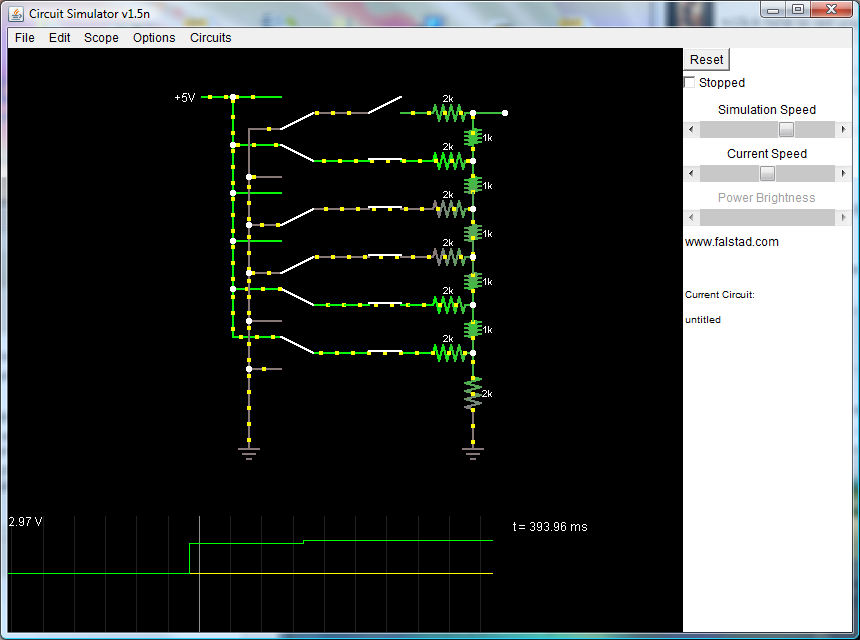
R-2R DAC Simulation
The R-2R DAC and analog comparator negative input can be simulated with the following text file, which can be imported into the Falstad.com Circuit Simulator Applet, found here: http://www.falstad.com/circuit/
(Copy text and paste into Import dialog in Circuit Simulator Applet) http://www.rev0proto.com/files/falstad_6-bit_tri-state_r2r.txt
Min/Max Resistor Voltage Divider Calculator
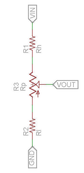
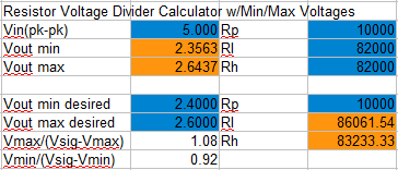
To generate a variable output voltage with minimum and maximum limits, I used the circuit shown to the right, and derived a formula to calculate the corresponding resistor values. For example, if you wanted to generate a reference voltage for a circuit that could be adjusted between 2.4V and 2.6V, given a 5V reference, you would type those limits into the lower part of the calculator, and the input voltage, in the blue boxes, specifying the resistance of the potentiometer, let's say 10k ohms. The calculator gives us a result of 86.06k ohms for the lower resistor, and 83.23k ohms for the upper resistor. Since we can't obtain those exact values, you can plug in the values of the resistors you have in the upper blue boxes, for example, the standard 10% value of 82k ohms gives us an upper limit of 2.644V and lower limit of 2.356V.
http://www.rev0proto.com/files/voltdiv_minmax.xls
PWL Function Generator (Work in progress)
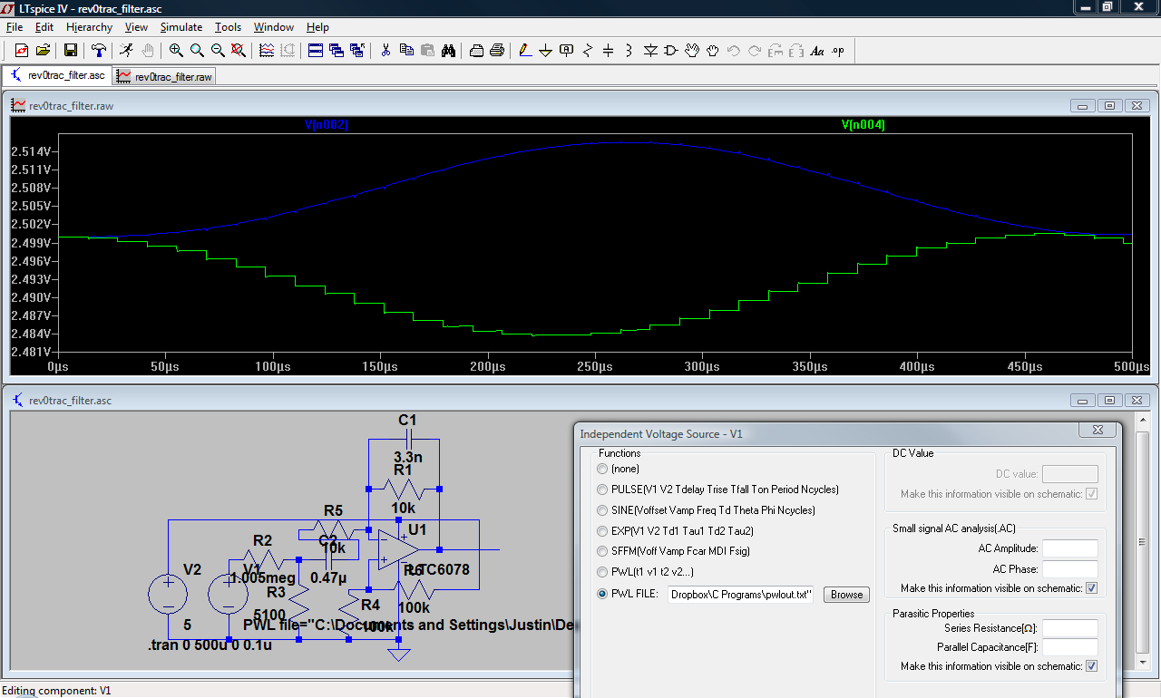
In order to more accurately simulate the effectiveness of the low-pass filter at rejecting high-frequency components of the DAC output, I used a C program to generate PWL text files for use with LTspice IV. I hope to expand the functionality of the program and rewrite it with a graphical interface, to allow it to serve as an arbitrary waveform generator for LTspice. Currently, the program is only configured to generate discrete cosines, and uses the rise time value for both rise and fall times of the waveform.
Usage:
- Open a command prompt via Start -> Run -> cmd
- Configure the following settings in "in.txt":
- Line 1: Amplitude (V)
- Line 2: Offset (V)
- Line 3: Frequency (Hz)
- Line 4: Sample Rate (Samples per cycle)
- Line 5: Rise Time (Seconds)
- Line 6: Fall Time (Seconds)
- Line 7: Resolution (bits, e.g. 8-bit DAC)
- Line 7: Waveform Type (c = Cosine, s = Sine, t = Triangle, w = Sawtooth; Positive Slope, m = Sawtooth; Negative Slope)
- Line 8: Data Length (Seconds)
- Change directory to location of pwlgen.exe
- Enter the following: "pwlgen.exe < in.txt > pwlout.txt"
- Open pwlout.txt and delete text before the data
- In LTspice IV, place a voltage source, right click it and select PWL file
- Browse to the location of pwlout.txt and select it
Executable: http://www.rev0proto.com/files/pwlgen.zip
Example input text file: http://www.rev0proto.com/files/in.txt
Source code: http://www.rev0proto.com/files/pwlgen.c
Eagle Schematic and Board Files
Schematic: http://www.rev0proto.com/files/aprs-2side_v11.sch
Board: http://www.rev0proto.com/files/aprs-2side_v11.brd
References
- ↑ The APRS Working Group, "APRS Protocol Reference". Available: http://www.aprs.org/doc/APRS101.PDF [Accessed 11/20/2011].
- ↑ APRSWiki, "Symbols and SSIDs". Available: http://info.aprs.net/index.php?title=SymbolsAndSSIDs [Accessed 11/20/2011].
