Puxing PX-2R
The Puxing PX-2R is a 70cm band (400-470MHz) handheld transceiver with a 2W maximum output power, 128 memory channels, a built in FM radio tuner, and various other standard features. The radio measures 84mm x 48mm x 25mm (3.3" x 1.9" x 1"), not including the antenna. It is powered by a 3.7V single-cell 1100mAH (Nokia BL-5C) battery, and can be charged via a USB port, with the included cable. It can be purchased from online retailers (direct from China) for approximately $50 USD, incl. shipping.
Comments
The radio is well built, with an internal metal chassis and heavy plastic construction, with metal threaded inserts for all screws. The radio has a couple significant bugs, the first being a noticeable click whenever the channel is changed or the speaker is activated. This is due to a ~2V DC offset being applied to the speaker every time it's switched on. The S-meter on this radio appears to only really work in the FM radio function, having no bearing on the actual signal strength of received UHF signals, and jumping around even when receiving strong/unchanging signals, and as noted by others, it continues to display after transmissions end. The DC plug on the radio has intermittent contact and only charges when it is angled or held a certain way. I recommend buying an external battery charger, which can be commonly found for the BL-5C Nokia battery. I have used a genuine Nokia BL-5C battery in the radio with success; the two appear perfectly interchangeable. The radio has the ability to receive and transmit on frequencies outside the US 70cm Amateur band (420-450 MHz), including many commercial and public service bands. To prevent unintended transmission outside the 70cm band when using the device to listen to these frequencies, it is highly recommended to use an offset to ensure any accidental transmissions remain in the allowed frequencies (e.g. -20 MHz to force a transmit on a 460 MHz station to 440 MHz).
Testing
All tests done at 445.925MHz
Power:
- High = 1.65W
- Low = 1.16W
Carrier Frequency Deviation:
- 150Hz (Narrow, Approx.)
Deviation:
- 2.2kHz (Narrow, Approx.)
- 5.4kHz (Wide, Approx.)
- 800Hz (PL Deviation, Wide, Approx.)
Receiver Sensitivity:
- 0.5uV (Approx.)
Current (At 3.7-4.0V):
- FM Radio = 110mA (Vol. approx 10%)
- RX Power Save/Idle = 25mA
- RX Idle = 81mA
- RX Active = 90mA
- TX Low Power = 723mA
- TX High Power = 1.14A
- Backlight = 34mA
Voltage:
- 3 bars: 4.0-4.2V
- 2 bars: 3.7-4.0V
- 1 bar: 3.4-3.7V
- Cut-out: 3.0V
Weight:
- PX-2R with battery, clip, antenna = 145.7g
- PX-2R with battery, clip, no antenna = 136.2g
- PX-2R with battery, no clip, no antenna = 131.0g
- PX-2R with no battery, no clip, no antenna = 108.9g
- PX-2R with no battery cover, no battery, no clip, no antenna = 98.3g
Teardown/Disassembly Procedure
- Step 1:
- Remove the volume and selection knobs

- Step 2:
- Remove the battery cover, battery, antenna, and screws at the bottom of the battery compartment

- Step 3:
- Remove the mic/speaker jack cover, lift out the unit from the bottom first, and remove the DC jack cover

- Step 4:
- Remove two screws holding the PCB to the chassis
- Pop out the tab holding the LCD to the PCB

- Step 5:
- Remove the LCD by tilting the up the LCD from the top first and lifting it out

- Step 6:
- Desolder and remove the backlight assembly (two pads on the right hand side of the PCB)

- Step 7:
- Unscrew the collar holding the knob assembly the the chassis
- Remove the two remaining screws on the PCB (under where the backlight assembly was)
- Remove the screw visible through a hole in the PCB (under where the backlight assembly was)
- Desolder the SMA connector on the right hand side of the PCB (under where the backlight assembly was)
- Lift out the PCB
- (You may find it easiest to apply heat to the SMA connector while lifting up the PCB once the solder is molten)

Component List
| Component | Additional Text | Manufacturer | Function |
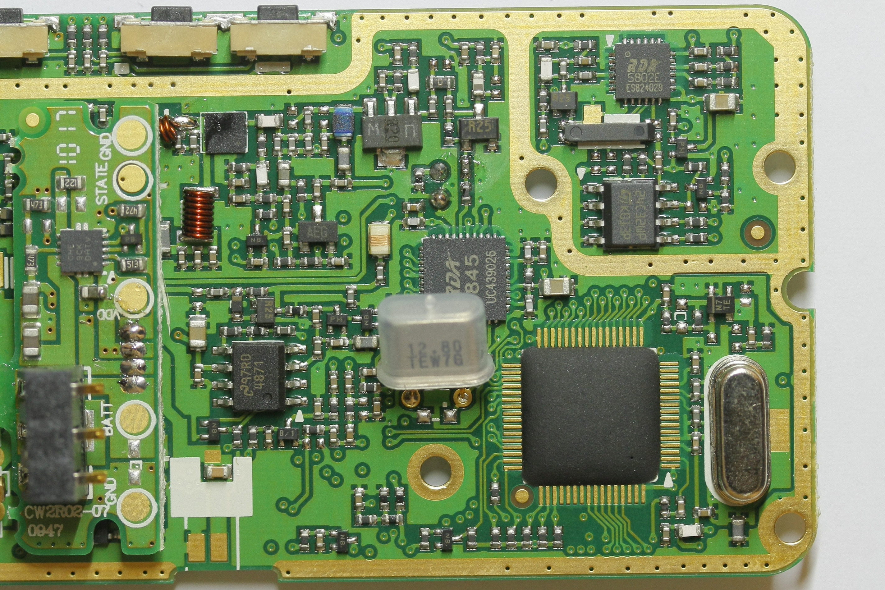
| RDA1845 | UC439026 | RDA - RDA1845 | Single chip transceiver, integrating synthesizer, IF selectivity and base-band signal processing. 10mW Output power. |
| RDA5802E | ES824029 | RDA - RDA5802E | Single chip broadcast FM stereo tuner, integrating synthesizer, IF selectivity and MPX decoder. |
| CHE 9CK DHTV | Unknown | Li-Ion battery/power management IC | |
| LM4871 | 97RD 4871 | National Semiconductor - LM4871 | 3W Audio Power Amplifier |
| 24C32WP | K013P | ST Microelectronics - M24C32-W | 32Kbit I2C Serial EEPROM |
| R25 | Unknown | Transistor/RF Amp/Preamp (?) | |
| U W | 020 | Unknown | Transistor/RF Amp/Preamp (?) |
| 03U3 | Unknown | RF Power Amp (?) | |
| <No Markings> | ASIC | Main controller IC, controls RF IC, FM Tuner, LCD, Battery, User Interface | |
| <No Markings> | ASIC | LCD controller IC | |
| 12.80 | TEW7G | Unknown | XTAL for RDA1845 |
| 4.00 | Unknown | XTAL for main controller ASIC |
I have acquired the datasheet for the main radio IC, RD1845, and interestingly, the comment posted on the forum with the datasheet download was the following: "Radio chip, the transceiver has a lot of indicators can not meet the national standard! Careful use!" The datasheet can be found here: http://rev0proto.com/files/RDA1845_datasheet_v1.1e.pdf Additionally, the registers and programming info can be found here (for more adventurous hackers): http://rev0proto.com/files/RDA1845_registers_v2.3.pdf
Audio 'Pop' Issue
As noted above, one of the major outstanding problems with the Puxing PX-2R is the loud click or pop that occurs when changing channels, and whenever audio is switched on or off. This is due to a rather large DC offset that can be seen on the headphone and speaker lines, measuring at ~2V. This issue is discussed in the LM4871 datasheet:
| In addition to system cost and size, click and pop performance is effected by the size of the input coupling capacitor, Ci. A larger input coupling capacitor requires more charge to reach its quiescent DC voltage (nominally 1/2 VDD). This charge comes from the output via the feedback and is apt to create pops upon device enable. Thus, by minimizing the capacitor size based on necessary low frequency response, turn-on pops can be minimized. Besides minimizing the input capacitor size, careful consideration should be paid to the bypass capacitor value. Bypass capacitor, CB, is the most critical component to minimize turn-on pops since it determines how fast the LM4871 turns on. The slower the LM4871’s outputs ramp to their quiescent DC voltage (nominally 1/2 VDD), the smaller the turn-on pop. Choosing CB equal to 1.0µF along with a small value of Ci (in the range of 0.1µF to 0.39µF), should produce a virtually clickless and popless shutdown function. While the device will function properly, (no oscillations or motorboating), with CB equal to 0.1µF, the device will be much more susceptible to turn-on clicks and pops. Thus, a value of CB equal to 1.0µF is recommended in all but the most cost sensitive designs. |
I have temporarily added a band-pass filter at the headphone speaker, using the existing R = 10O, CL = 1.0µF, CH = 4.7µF, which has helped the issue significantly, although a higher cutoff frequency on the high-pass filter helps to further remove the effect, the components were selected as a compromise for audio bandwidth and the components on hand. The schematic for the PX-2R's audio amplifier circuit is shown below:

Additional Photos
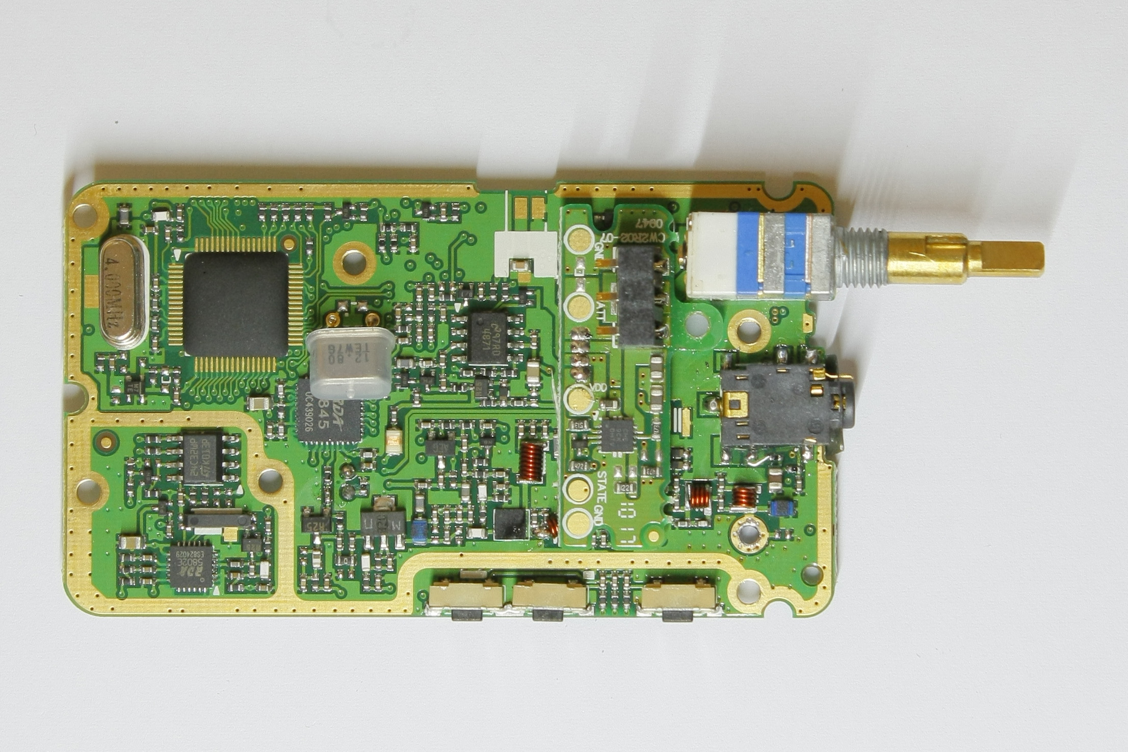
Main PCB
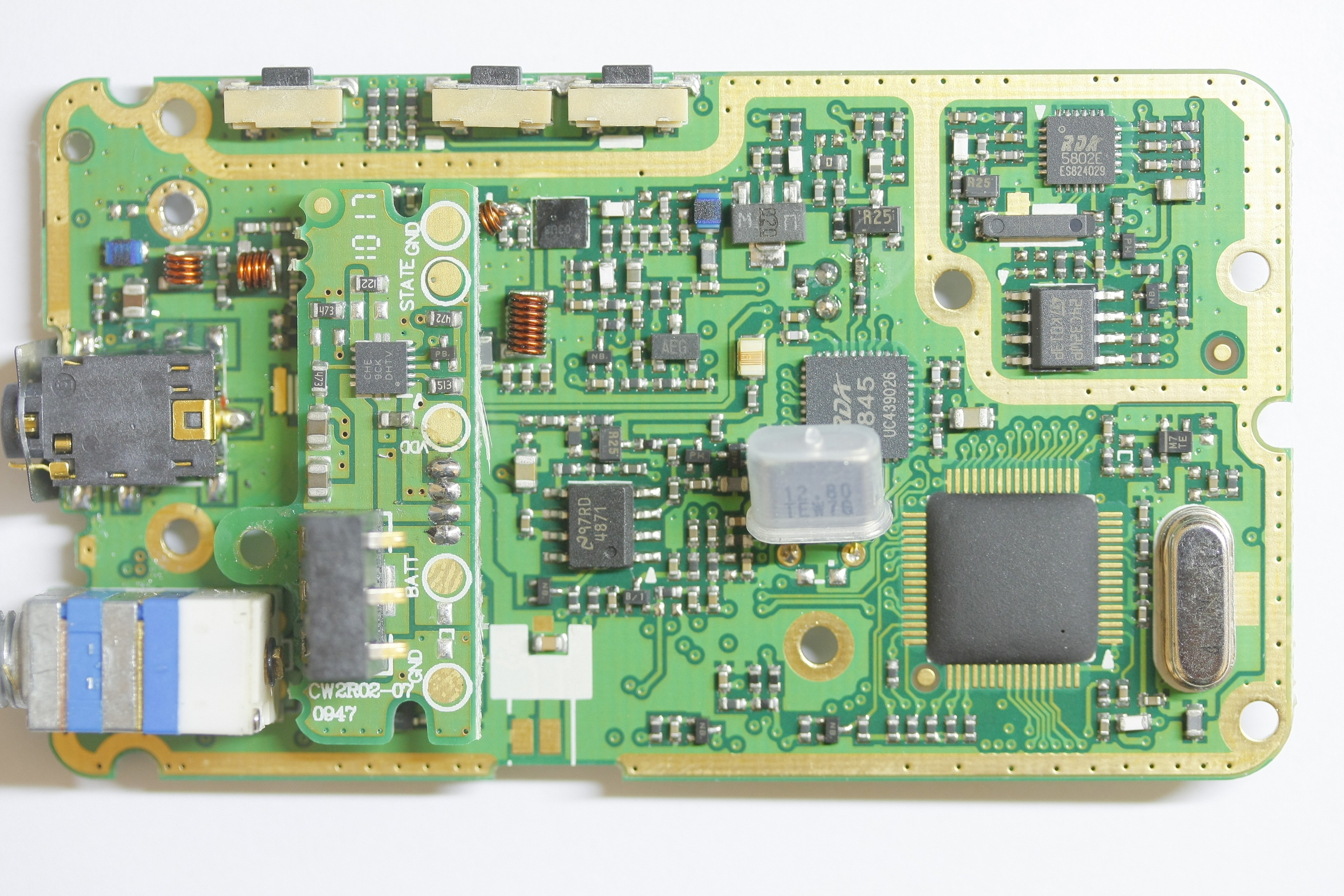
Main PCB
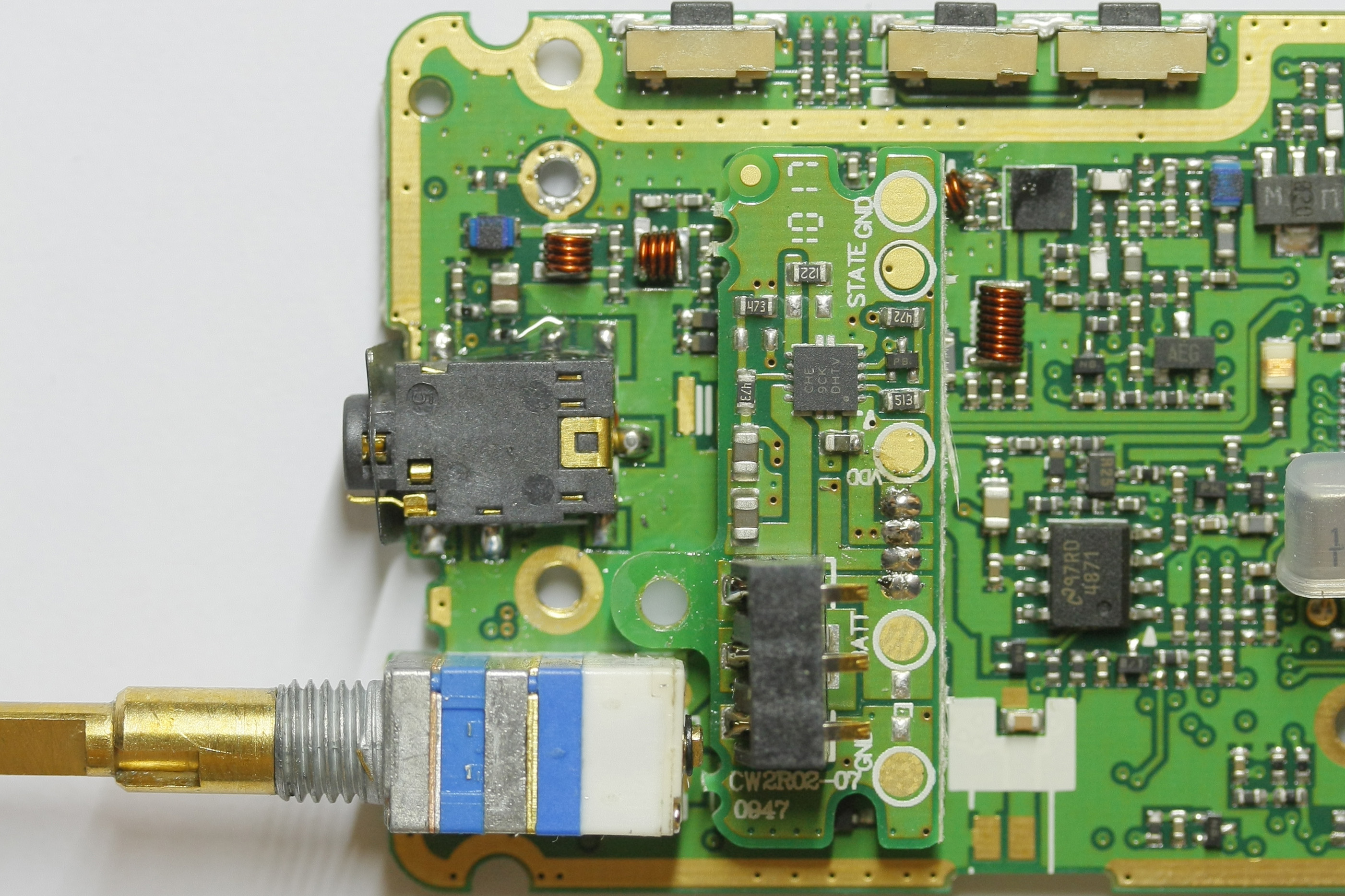
Battery PCB
Lower section of main PCB
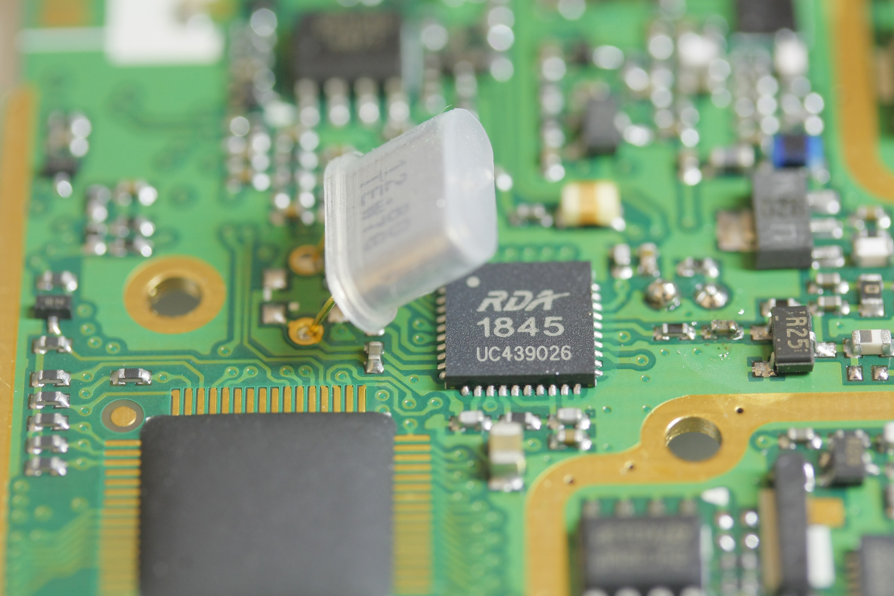
RDA1845--Transceiver IC
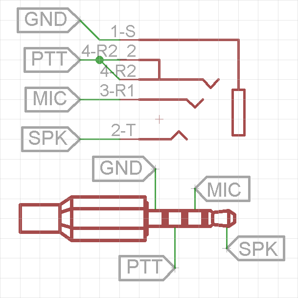
PX-2R audio jack pinout


