MICRF112
Summary
I designed and built a test board for the MICRF112 433MHz transmitter IC by Micrel, based on the example circuit given in the datasheet. After performing a basic test of the device, I modified the circuit to allow tuning of the reference crystal by means of a variable capacitor. After determining the frequency vs. voltage characteristics of the device using a spectrum analyzer and power supply, I determined the voltages needed to produce a 4.8kHz FM deviation. Using a signal generator, I produced 400Hz, 1.2kHz, and 2.2kHz tones and measured their FM spectra using a spectrum analyzer.
Circuit Schematic and Theory
The MICRF112 is a single-chip ASK/FSK transmitter IC designed for short range devices.[1] Short range devices are defined by the European Telecommunications Standards Institute (ETSI) as “radio devices that offer a low risk of interference with other radio services, usually because their transmitted power, and hence their range, is low.”[2] The device allows data to be transmitted via amplitude shift keying (ASK) or frequency shift keying (FSK), via two pins. RF is generated by an on-board 32x PLL, using an external crystal or reference frequency as the input. An internal power amplifier allows output powers of up to +10dBm.
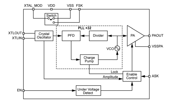
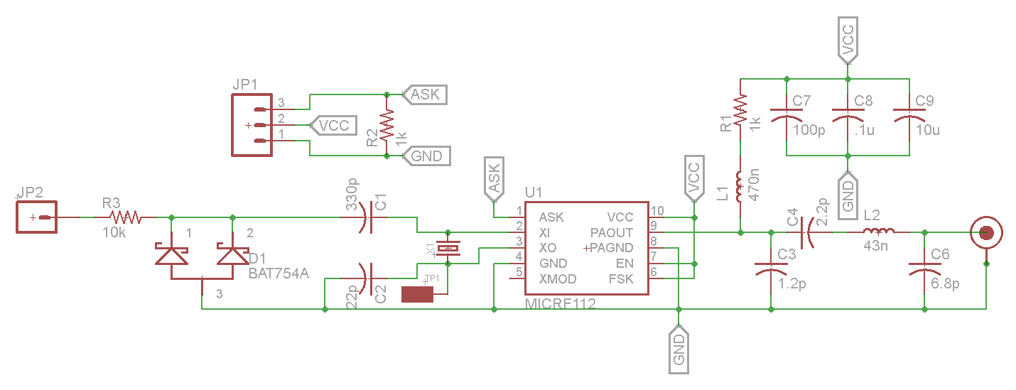
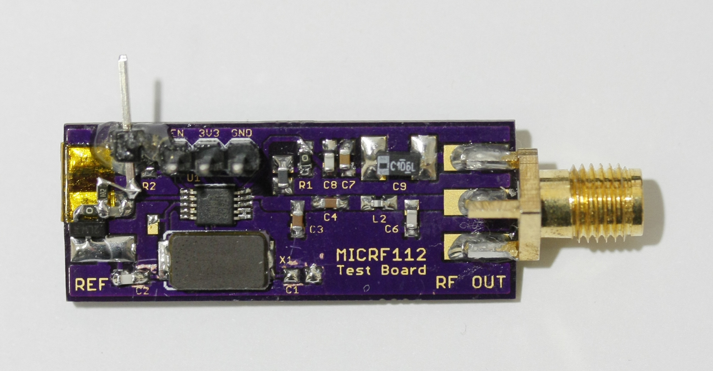
A block diagram for the device is shown in Figure 1 below. The circuit schematic (shown in Figure 2) is based on the application circuit given in the device datasheet. The datasheet suggested matching network was used to match the device to 50O, connecting to an SMA port. Power, ground, and the ASK pin (device enable) are routed to external pins, and a test point and SMA port are routed to the crystal output and input, respectively.
The circuit was modified to allow modulation of the reference frequency by pulling the crystal using the capacitors C1 and C2. A varactor diode replaces C1, and a tuning voltage is applied through a 10k resistor. The varactor diode was chosen, based on availability and capacitance range, to be a Philips BAT754 dual Schottky diode. A graph of the capacitance vs. reverse voltage is shown in Figure 3.
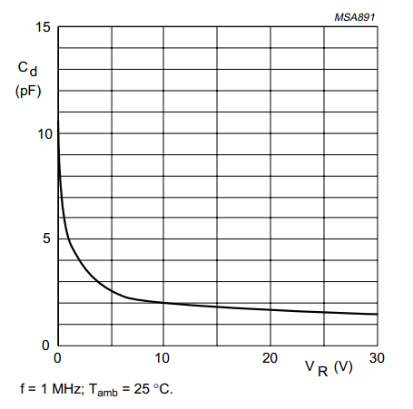
Using both diodes in the BAT754 in parallel, a capacitance range of approximately 20pF to 5pF could be achieved using a 0-5V tuning voltage. This is within the range of load capacitance needed by the 13.56MHz reference crystal used with the device. The modified circuit is shown in Figure 4. The final circuit is shown in Figure 5.
Testing
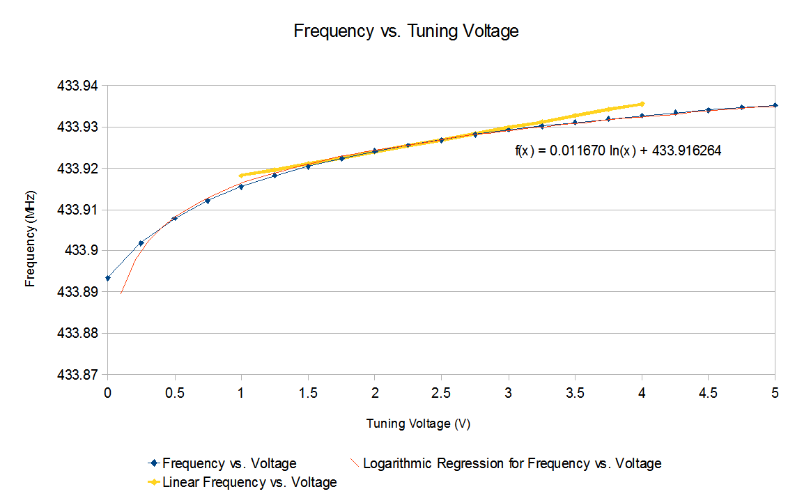
A table of frequency vs. tuning voltage was then recorded using an HP 8922M spectrum analyzer to measure the carrier frequency, and varying the tuning voltage using a power supply. A graph summarizing the results is shown in Figure 6.
A logarithmic regression was applied to the data to obtain a curve with the following formula:
Where v is the tuning voltage in volts, and F(v) is the resulting frequency. Taking a derivative, we can determine the FM deviation vs. bias voltage of the overall system:
A typical VHF/UHF FM transceiver uses a deviation of 4.8kHz when transmitting voice, thus 4.8kHz was chosen to be the desired deviation. A bias voltage of 2.5V was chosen to remain within the power rails of 0-3.6V and provide the best linearity within that voltage range (higher voltage provides better linearity). Using the derivative at 2.5V yields a required voltage swing of 1.03V for an FM deviation of 4.8kHz. Thus the minimum and maximum voltages are 1.99 and 3.01V. Solving for frequency using the first formula yields an actual minimum and maximum frequency of 433.9243 and 433.9291MHz, giving a true deviation of 4.87kHz, very close to the desired estimate. The frequency vs. voltage assuming a linear response is shown on the graph in Figure 6, demonstrating the error over the range of 1-4V. A signal generator was used to produce 400Hz, 1.2kHz, and 2.2kHz tones with a 1.03Vpp amplitude and 2.5V offset. The spectra were then measured, as shown in Figure 7.
The bandwidths of the three tones were measured to be 10.3, 9.6, and 13.9kHz, respectively. According to Carson’s rule, the expected bandwidth is:[4]
Where ∆f is the FM deviation, and fm is the modulating frequency. The bandwidths expected are thus 10.4, 12, and 14kHz. The actual bandwidths of the 400Hz and 2.2kHz tone closely match the expected bandwidths, with an unknown deviation from the expected with the 1.2kHz tone.
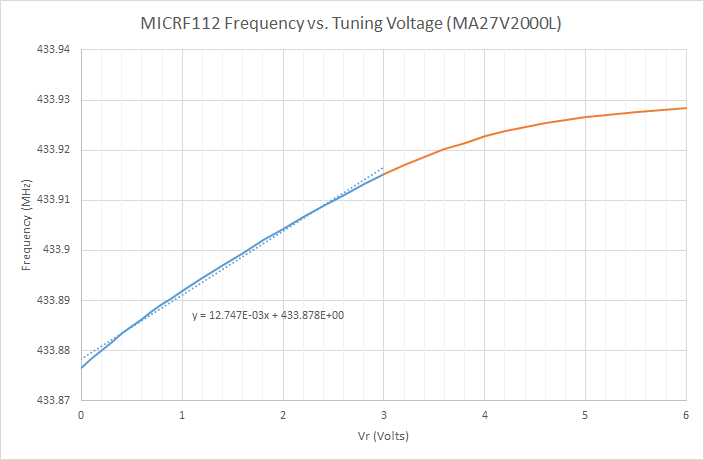
Using a different varactor diode (Panasonic MA27V2000L) optimized for low voltage systems resulted in a more linear frequency vs. tuning voltage curve, and allowed a total frequency delta of 38.5 kHz across a 3V range. The resulting plot is below:
Taking a linear approximation over the voltage range of 0-3V, the following formula was obtained:
Where v is the tuning voltage in volts, and F(v) is the resulting frequency. Thus the FM deviation vs. bias voltage of the overall system:
Using the equation above for 4.8 kHz deviation, the voltage swing required is 0.753Vpk-pk, centered around 1.5V.
Conclusions
The MICRF112 demonstrates that a simple analog FM transmitter can be created using a low-cost transmitter IC as a PLL and amplifier block in a simple indirect FM modulator. By applying a modulating signal to a varactor, the reference crystal was frequency modulated, producing a larger deviation FM modulated RF signal at the output of the device. The device can be turned into an APRS transmitter by injecting an APRS signal at the modulation input, once conditioned to 1.03Vpp and 2.5V DC offset. The device used in this prototype is locked to 32x the frequency of the reference crystal, limiting its capability. However, other devices, such as the ADF7012 by Analog Devices, implement a fractional-N PLL, allowing many RF frequencies to be generated. The next prototype will use the ADF7012 and a 20MHz VCXO, however a crystal and varactor setup has been confirmed to work, and could replace the VCXO in future versions.
References
- ↑ 1.0 1.1 Micrel Inc., "MICRF112 QwikRadio UHF ASK/FSK Transmitter," December 2011. [Online]. Available: http://www.micrel.com/_PDF/micrf112.pdf. [Accessed 22 January 2012].
- ↑ ETSI, "Short Range Devices," 2011. [Online]. Available: http://www.etsi.org/website/Technologies/ShortRangeDevices.aspx. [Accessed 22 January 2012].
- ↑ NXP Semiconductors, "BAT754 series Schottky barrier (double) diodes," 25 March 2003. [Online]. Available: http://www.nxp.com/documents/data_sheet/BAT754_SERIES.pdf. [Accessed 22 January 2012].
- ↑ Adrio Communications Ltd., "Frequency Modulation Bandwidth, Spectrum & Sidebands," [Online]. Available: http://www.radio-electronics.com/info/rf-technology-design/fm-frequency-modulation/spectrum-bandwidth-sidebands.php. [Accessed 22 January 2012].

