GC-D 1000
This is a project to create a fully functional, production-ready digital Geiger counter. It builds on the features of the GC-D 100, including the change to a graphic LCD, USB rechargable LiPo battery, USB upgradable firmware, significantly lower power usage, and the move to a lower cost and more common Geiger tube, all at around 80% of the cost of the original.

List of Features
- Custom product enclosure designed with Autodesk Inventor and manufactured by Shapeways
- 84*48 Graphic LCD
- SI3BG Geiger Tube
- Click and Bi-Color LED radiation indicator
- Re-programmable and rechargable via micro-USB
- Two selectable units: Röntgen or Sievert
- Manual count mode with timer
- Accumulated Dose display
- Battery gauge
- Internal 1000mAH LiPo battery
- 24 Hour battery life
Electronics

High Voltage and Geiger
The high voltage DC is generated by a standard boost converter topology operating in PFM. An ATtiny10 microcontroller produces a 31250 Hz PWM waveform with a duty cycle of 94.9% (242/255), which switches a 600V 10.1A N-channel MOSFET. Current is directed through the inductor every on cycle, which stores electrical energy in the magnetic field of the inductor. On the off cycle, the magnetic field collapses, and the energy stored is directed through two series 400V 1A US1G diodes, and into the 0.1uF ceramic capacitor. The output voltage is regulated to a fixed 400V through a closed-loop feedback system. A divided output voltage is read by the ATtiny10. If the voltage exceeds the upper limit (425V), the PWM output is disabled. When the voltage falls below 400V, the PWM output is enabled. This high voltage is then applied to the anode of the Geiger tube through a 10M ohm resistor. The cathode is connected to ground through a 200k ohm resistor. When a high energy particle (in this case, a gamma ray) passes through the tube, it strikes the intert gas molecules inside, knocking electrons off in the process. These electrons carry enough energy to knock electrons off other molecules, producing a chain reaction called an avalanche. A halogen gas inside the tube replenishes electrons and prevents the tube from being stuck in the conducting mode. The 400V applied to the Geiger tube produces a high potential, which accelerates electrons toward the anode, producing a current. This current flows through the 200k ohm resistor and produces a voltage drop, which is filtered and buffered, then detected by the microcontroller, and represents one count.
Microcontroller and LCD

In the simplest case, a digital Geiger counter would need only two functions, to count the pulses from the Geiger tube and calculate a rate, and to display the rate on the LCD. This project simply adds a few extra features, all very simple to implement. First, the microcontroller needs to be able to count pulses from the Geiger tube over a certain time period. This is accomplished by running a timer divided down from a 24 MHz crystal. Pulses are detected by the microcontroller's hardware via a falling edge interrupt, which increments the ticks variable. The timer module produces an interrupt 50 times a second. Every second the microcontroller records how many pulses were detected since the last interrupt, and this value is added to an array of 32 values each 0.3s, which are averaged and displayed. Next, the microcontroller needs to display values and text to the screen. This is achieved by sending binary data over an SPI data interface. An LCD function library handles the low-level conversion between ASCII characters from strings or numbers in variables to characters to be displayed to the LCD. The microcontroller reads battery voltage and displays it as an 8-level bar graph. The microcontroller also optionally displays conversions in uSv/H and mR/H, and displays the corresponding accumulated dose (uSv in CPM mode). The microcontroller also maps the CPM value to a logarithmic bar graph, which is displayed in the middle of the screen.
Hardware Revisions
Revision 1.0
This is the first revision of the GC-D 1000.
Revision 1.1
This is the second revision of the GC-D 1000, correcting several flaws in the circuit as well as enclosure, listed below:
PCB:
- Geiger tube signal routed to input pin with edge triggered interrupt
- USB port moved lower to accomodate enclosure design
- Voltage sense pin tied directly to VBAT allowing voltage read when switched off but plugged in (charging)
Added auto power-off capability (MCU signal to boost EN line)Removed, battery monitor should be sufficient.- Added LiPo battery monitor circuit
Enclosure:
- Added space at top of enclosure for second SI3BG size (short/wide vs. thin/long)
- Increased clearance along edge seal for better fit
- Increased tolerances for better fit of PCB and edge snaps
- Modified magnet holders
- Improved buttons to add reach and fit in holes
- Increased hole size for PUR button access (USB program button)
- Minor cosmetic/structural improvements
Outstanding Issues:
- The buttons are currently not manufacturable by Shapeways. They must be redesigned (a rectangular slot/profile would be a better approach) to have increased wall thickness.
Revision 1.2 (Planned)
This is the third revision of the GC-D 1000, adding the option for an external probe (e.g. LND-382) for greater sensitivity.
PCB:
- Switch to boost-doubler topology (allows for simultaneous 400/800V supplies).
- Added accessory port for external Geiger probe
- Added mux to switch between Geiger tube outputs
Enclosure:
- Added slot for external probe
- Redesigned buttons with rectangular profile and thicker walls
- Decreased clearance for PCB holder
- Added short internal guide tube for USB Boot pin to make pressing the button easier
- Added small nubs on rear of device to prevent case from being scratched if moved along a rough surface
- Added logo and button/switch text
PCB Files
Here is the Eagle schematic file for the GC-D 1000: http://rev0proto.com/files/GC-D_1000_v02.sch Here is the Eagle board file for the GC-D 1000: http://rev0proto.com/files/GC-D_1000_v02.brd
Enclosure
The enclosure for the GC-D 1000 was created with Autodesk Inventor 3D CAD software, and manufactured using rapid prototyping through Shapeways. Dimensions for all major parts and the PCB were taken from their respective datasheets or by using a digital caliper, and 3D representations were made in Inventor. Then the basic shape for the enclosure was devised, and it was created with the constraints given by the parts needed. The enclosure is made of 5 separate pieces, which are assembled by snapping them together.
Here are the Autodesk Inventor files for the GC-D 1000: http://rev0proto.com/files/GC-D_1000_Model.zip
Code
Full source code for the project can be found here: http://rev0proto.com/files/gc-d_1000.zip
Comparison to GC-D 100
The first change I wanted to make on the GC-D 100 was the battery. With my previous experience from the rev0Trac VTx, I decided to use a single-cell 1000mAH LiPo for the GC-D 1000. The primary constraint for the batteries for the GC-D 100 was the voltage needed for the step-up converter. By optimizing the boost converter design, both through simulation and breadboard prototyping, I was able to design a circuit that would operate down to the LiPo minimum of 3.0V (the boost converter can operate down to 2.6V in practice). This allowed the device to operate on a single cell, eliminating the challenges of balancing and charging a dual-cell LiPo. The voltage for the ATtiny10 microcontroller is still provided by a 5V synchronous boost converter, and is needed to operate the MOSFET efficiently (high enough voltage to operate in saturation).
The high voltage circuitry in the GC-D 100 was scattered throughout the PCB layout, a potential danger when operating the device without the case, and a potential danger to the low-voltage circuitry surrounding it. The GC-D 1000 was routed such that the high voltage circuitry is spatially isolated in the bottom section of the PCB, clearly marked by silkscreen. I chose not to optically isolate the two sections due to the low selection of high-speed opto-isolators and the packages they are available in. The boost converter is operated by an independent microcontroller, freeing up cycles and adding an extra layer of isolation to the application MCU. The Geiger tube output is fed through a Schmitt inverter to clean up the signal and also provide isolation from the Geiger tube.
Drawing again from my experience with the rev0Trac VTx, the GC-D 1000 uses a Nokia 5110 graphic LCD. In addition to giving more freedom with displaying information, it is thinner, cheaper, and much lower power than the 8x2 character LCD used in the GC-D 100.
This device was designed on a smaller timeline (~6 weeks) than the original and optimized for cost and manufacturability, thus some of the more exotic features, such as location logging are left out. This device nevertheless uses a more powerful microcontroller, programmable over USB, and has much greater potential for expansion.
Videos
<HTML5video type="youtube" width="400" height="300" autoplay="false">1SHY4jAfTcM</HTML5video> <HTML5video type="youtube" width="400" height="300" autoplay="false">nnFNTOPaNV0</HTML5video>
Photos
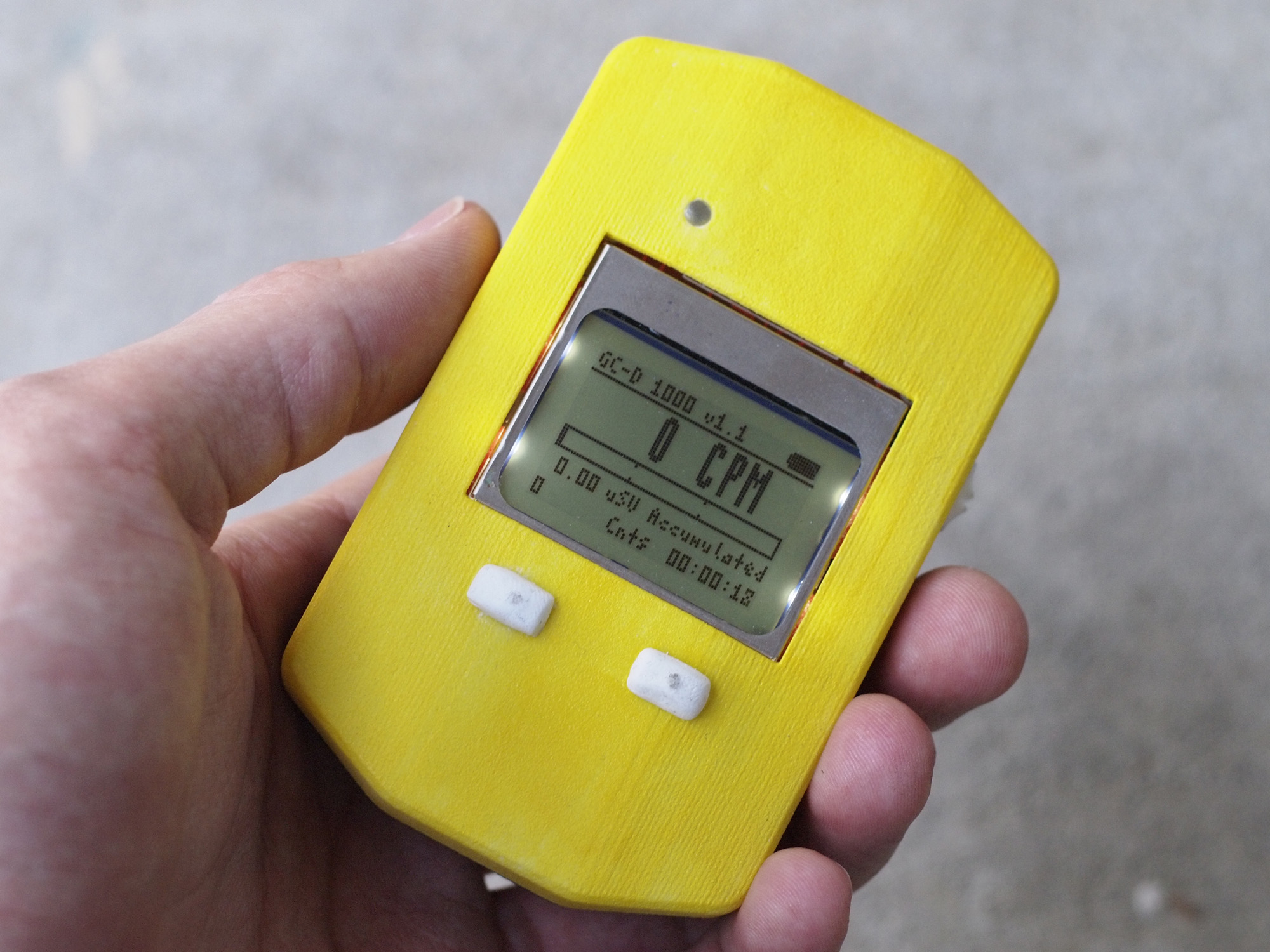
GC-D 1000 Handheld
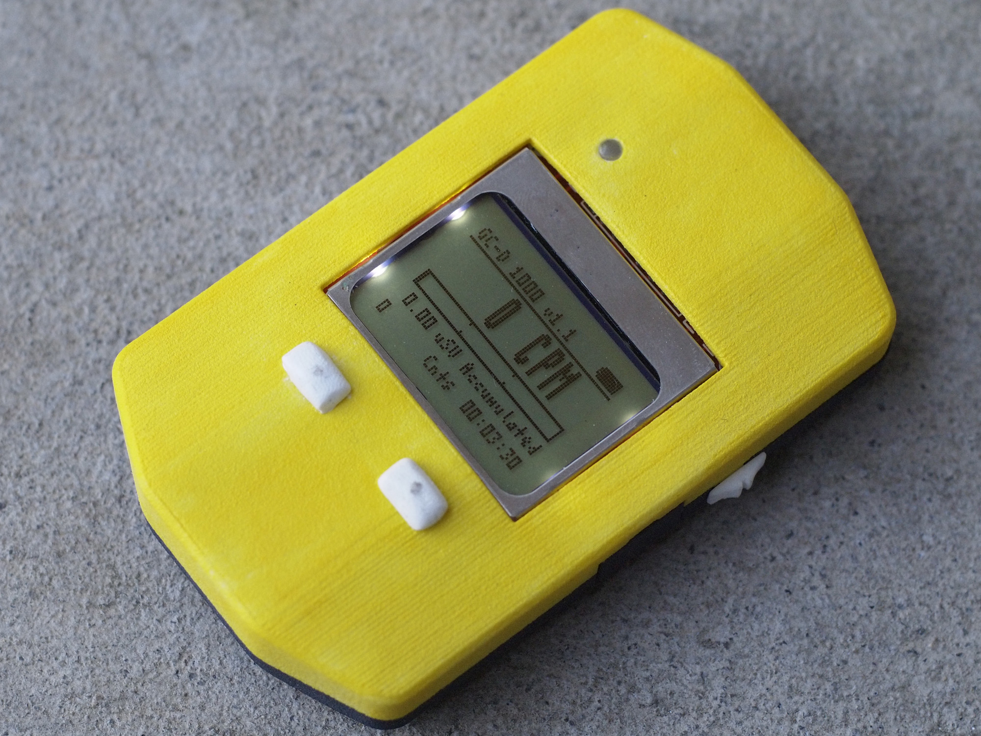
Top view of the GC-D 1000
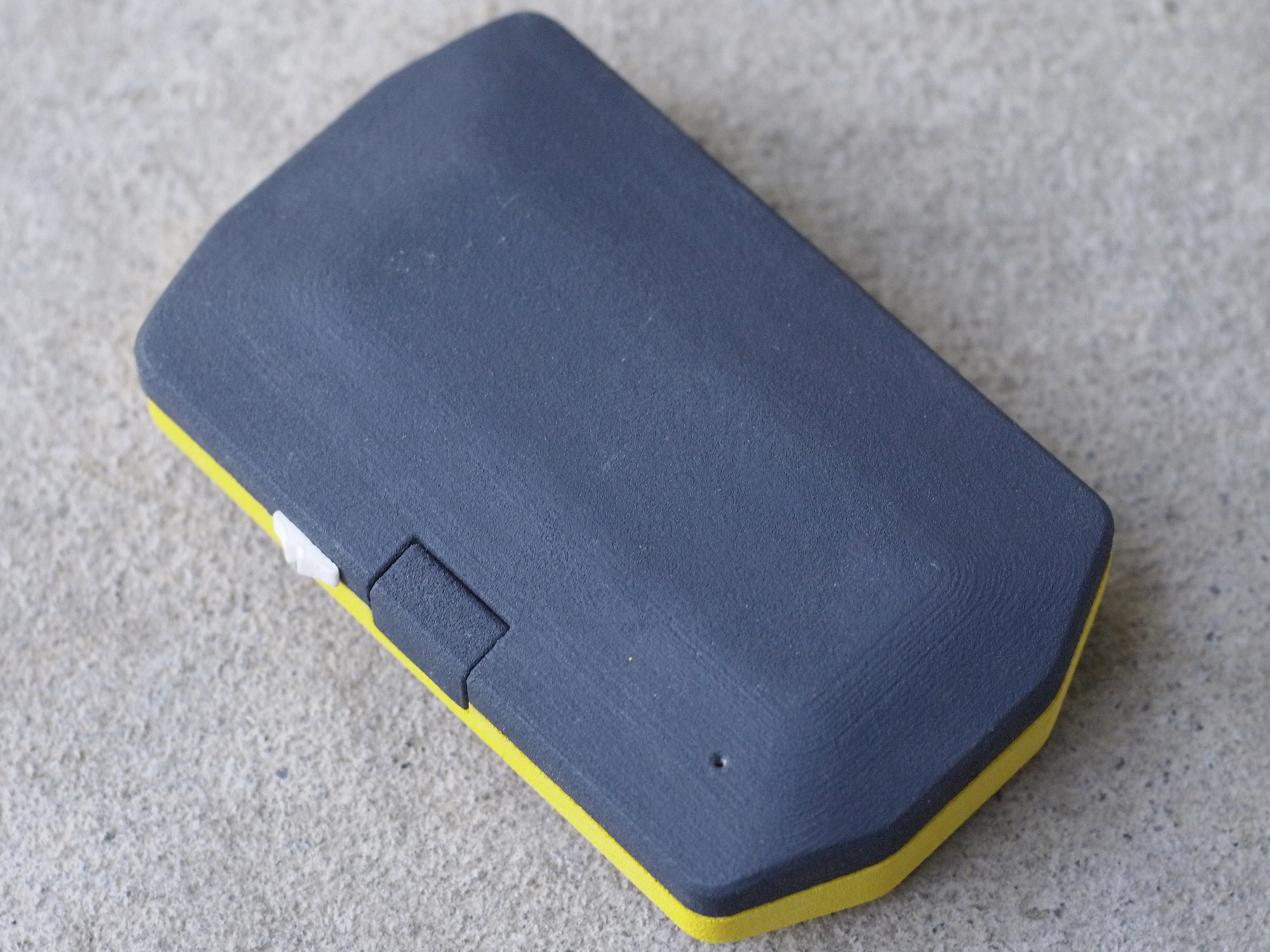
Bottom view of the GC-D 1000
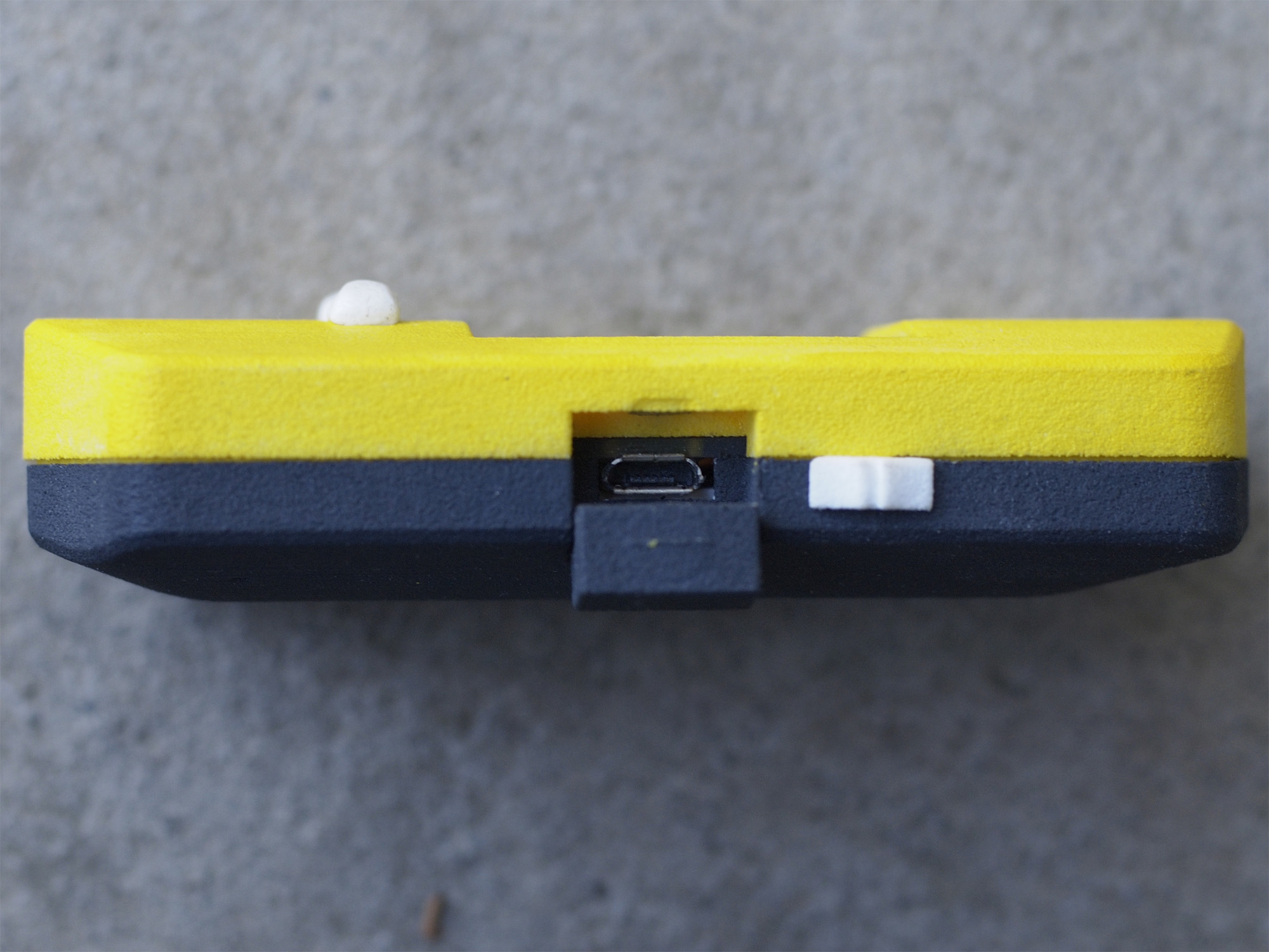
Side view of the GC-D 1000


Total Project Cost
| Component | Cost | Source |
| Enclosure (Top) | $19.03 | Shapeways |
| Enclosure (Bottom) | $22.33 | Shapeways |
| Enclosure (Buttons/Switch/Cover/Shipping) | $20.65 | Shapeways 123 |
| PCB | $8.40 | OSH Park |
| Geiger Tube | $7.44 | eBay |
| Battery | $4.04 | HobbyKing |
| Components | $25.86 | Digi-Key |
| Total Price | $107.75 |