X2 Mill: Difference between revisions
| Line 4: | Line 4: | ||
==3D Model== | ==3D Model== | ||
. | A 3D CAD model of the Sieg X2 along with CNC additions is available at GrabCAD here: https://grabcad.com/library/sx2-mini-mill-cnc | ||
==Setup/Modifications== | ==Setup/Modifications== | ||
Revision as of 22:58, 8 December 2015
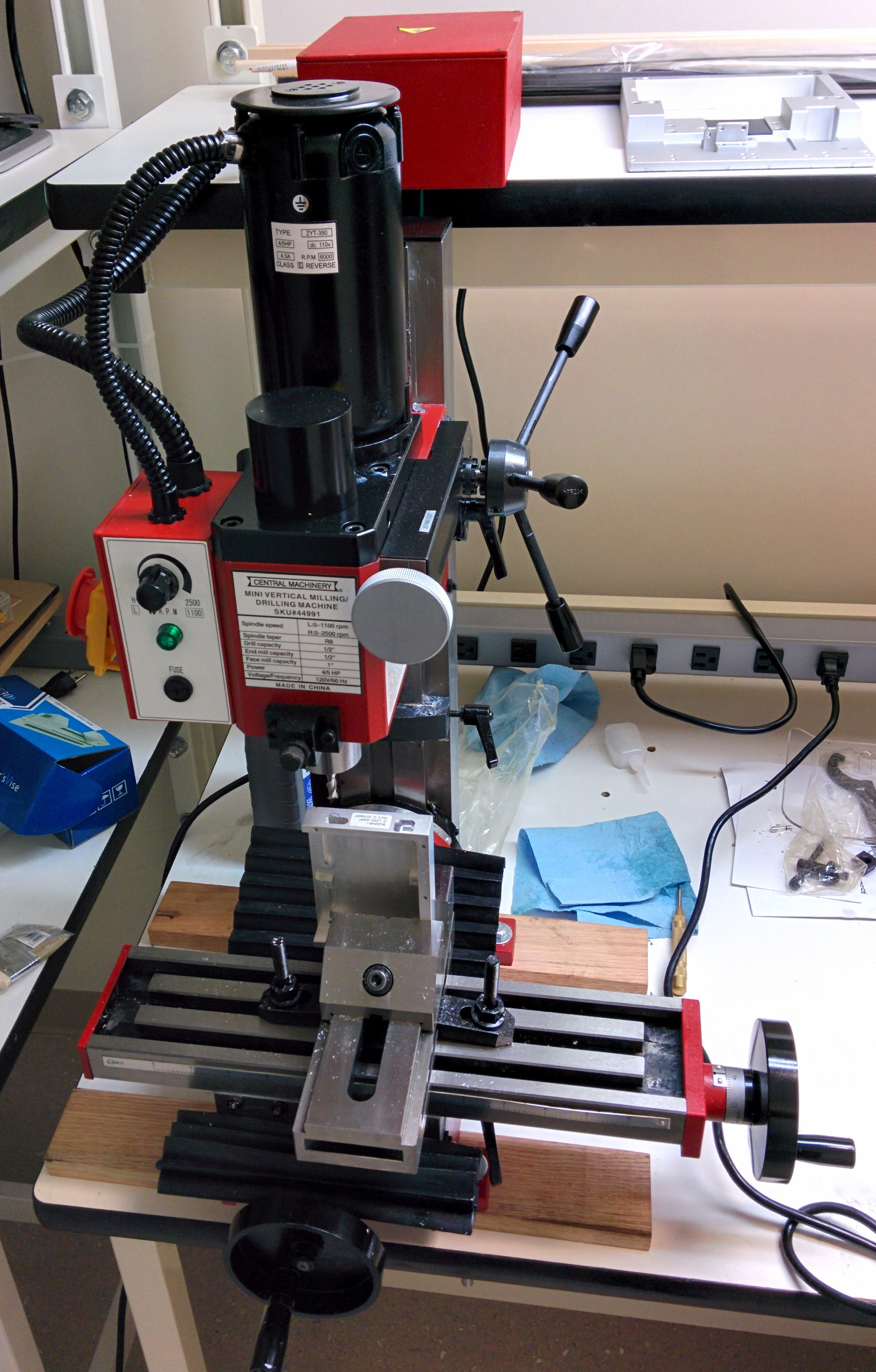
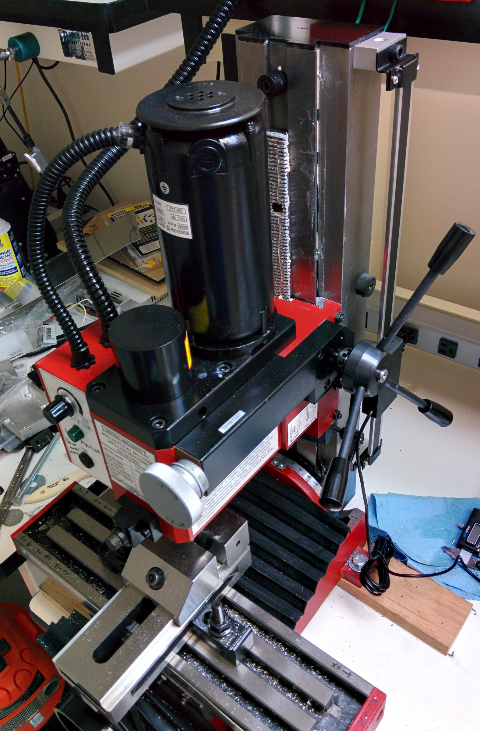
This page documents the setup and modification of the Harbor Freight Mini Mill (Sieg X2 Clone).
3D Model
A 3D CAD model of the Sieg X2 along with CNC additions is available at GrabCAD here: https://grabcad.com/library/sx2-mini-mill-cnc
Setup/Modifications
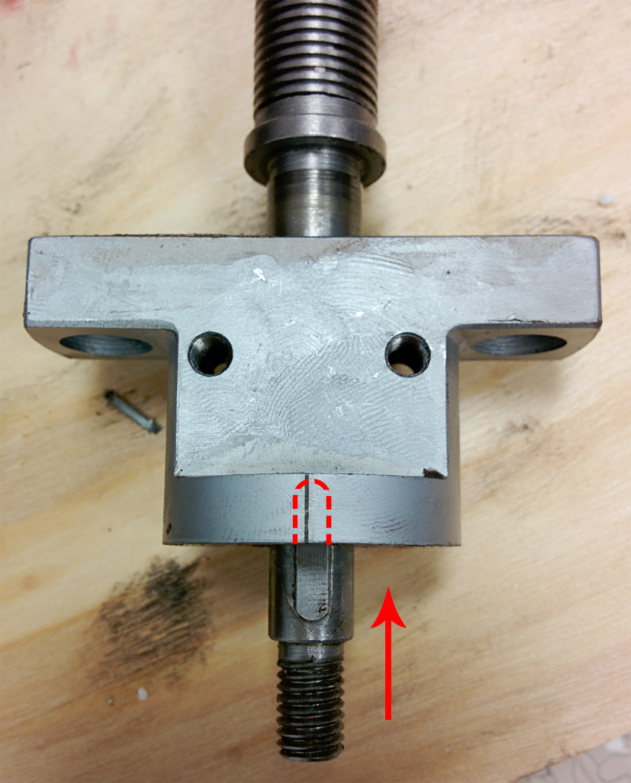
11/12/2015 - Harbor Freight Mini Mill arrives; damaged in shipment, both hold-down bolts came loose and the unit was dropped on the Y axis jamming the notch into the bearing/sleeve thus preventing any movement of the Y axis. Contacted customer service who made a note to return the mill to a local store and get a receipt to place a replacement order.
11/13/2015 - Damaged mill returned to Harbor Freight.
11/16/2015 - Replacement mill ordered by phone, shipping charge was waived since it was not refunded by the store with the damaged unit return.
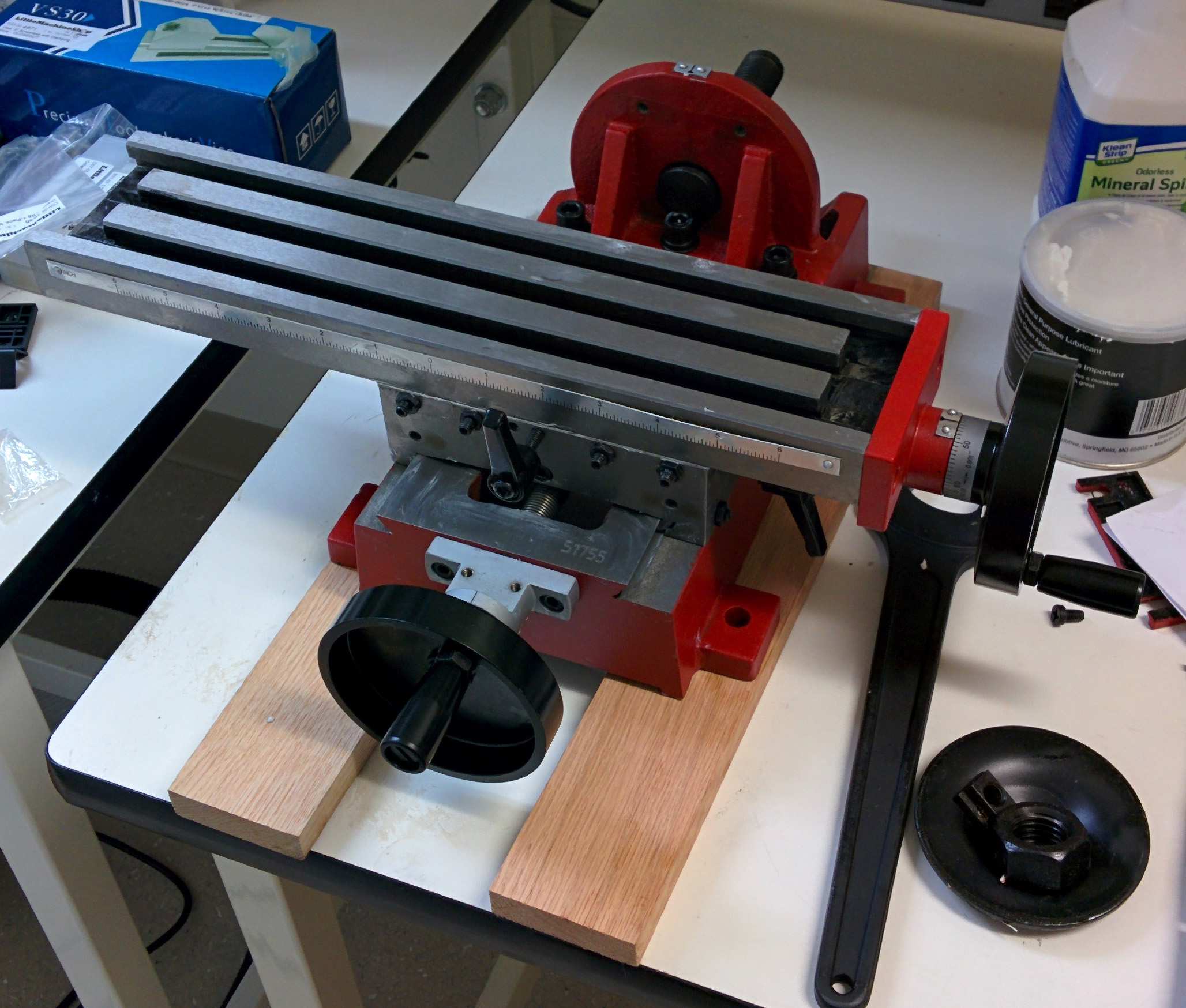
11/20/2015 - Replacement mill arrives, was only held down with one bolt (which was loose), but undamaged. Stripped down unit, cleaned, and lubricated Y and X axes and adjusted gibs.
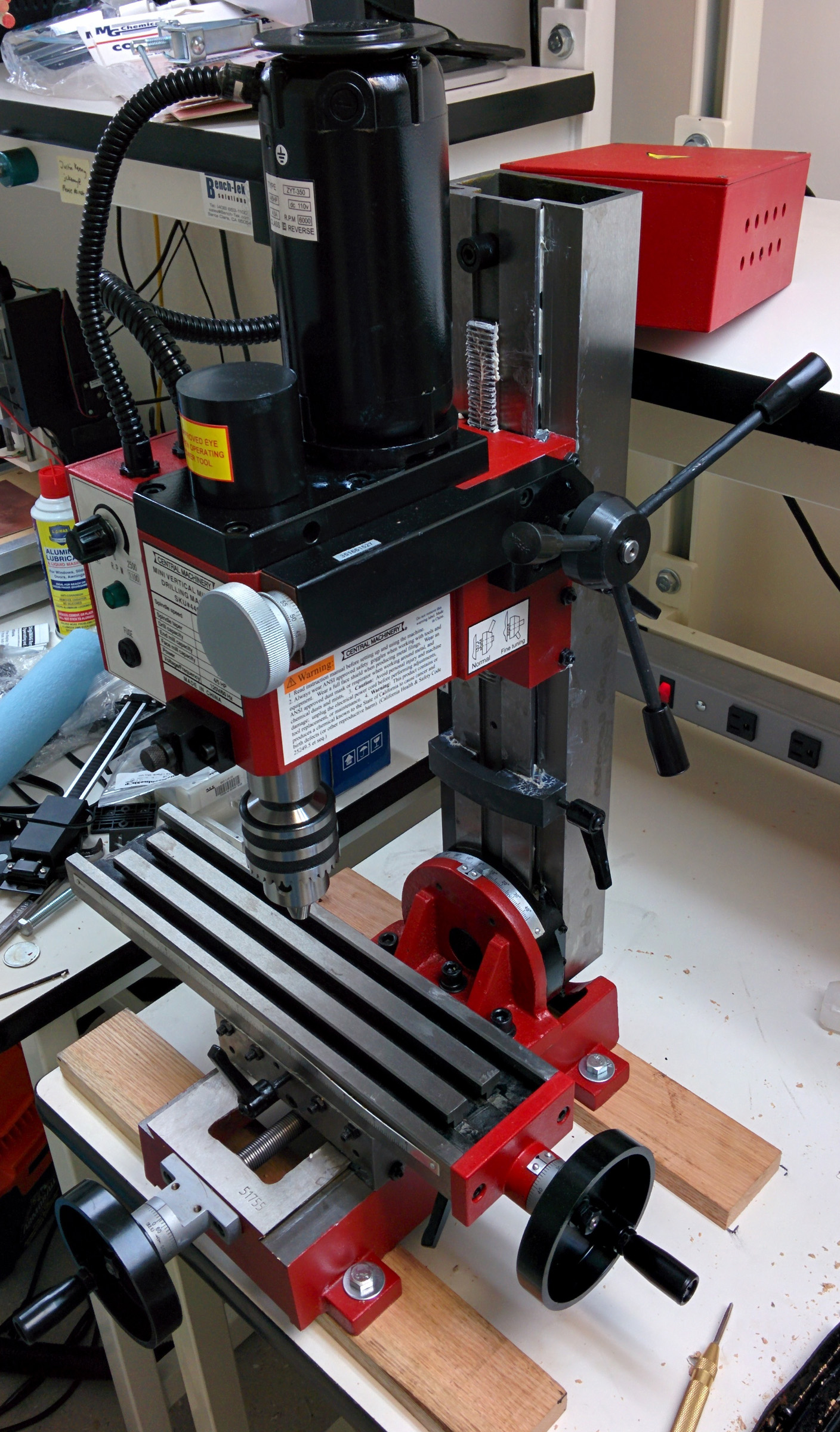
11/22/2015 - Stripped and cleaned Z axis/mill head, lubricated and adjusted gibs, and partially mounted unit to bench. Removed power supply box from back as it interfered with the shelf on the bench.
11/30/2015 - Fully mounted unit to bench, re-adjusted gibs.
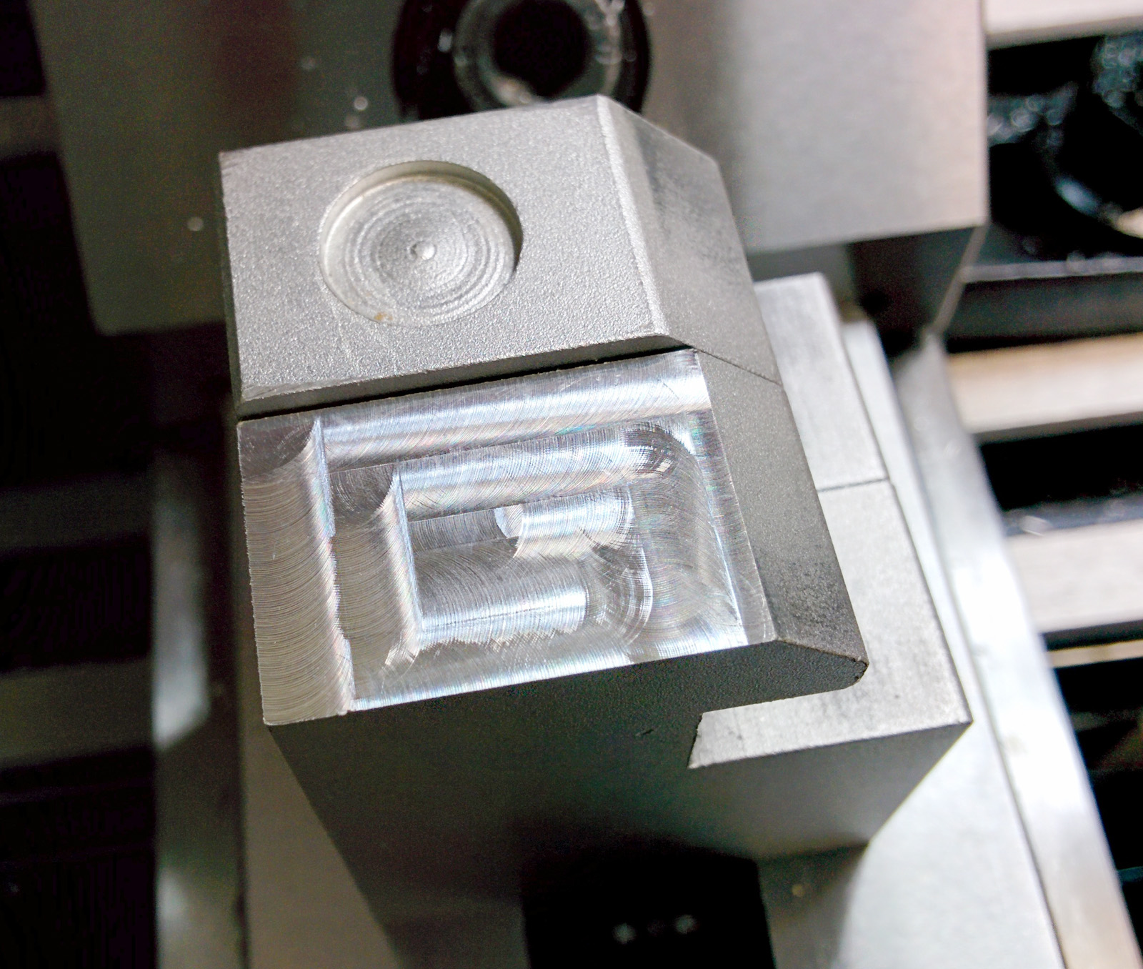
12/4/2015 - Mounted and squared vise, adjusted motor gear meshing, re-attached baffles, removed drill chuck and attached 3/8" R8 collet. Made first cuts in aluminum (shown below).
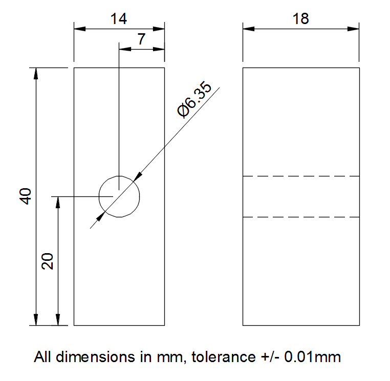
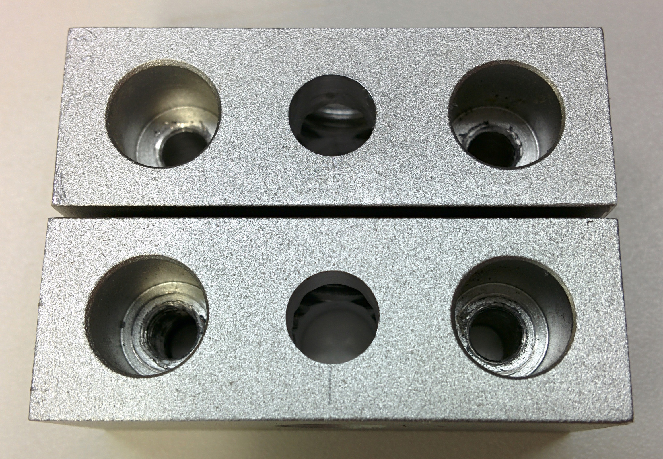
12/7/2015 - Milled holes in 2 aluminum pieces to be used as spacers for mounting the Z-axis DRO. Drilled and tapped 2 M6 holes in mill column, mounted Z-axis DRO fixed portion. Mounted vise properly using step blocks.
