Ryobi40V
Jump to navigation
Jump to search
This is a basic analysis of how a Ryobi 40V smart charger (model number OP403) communicates with the battery's BMS to enable the charging FET.
Electronics
Pictures of the charger PCB are below:


The wall wart adapter is a 42V 1.5A rated switching converter, listed at 84W max from AC (though output is max 63W). The wall wart does the necessary CC/CV current limiting, with a ~44.2V open circuit voltage output when no battery is connected. Output is switched to the battery though a MOSFET.
Charging Sequence:
File:Ryobi 40VChg Sequence Main.jpg
Battery insertion to charging start sequence.
Data detail:
File:Ryobi 40VChg Packet.jpg
Data packet detail.
Photos
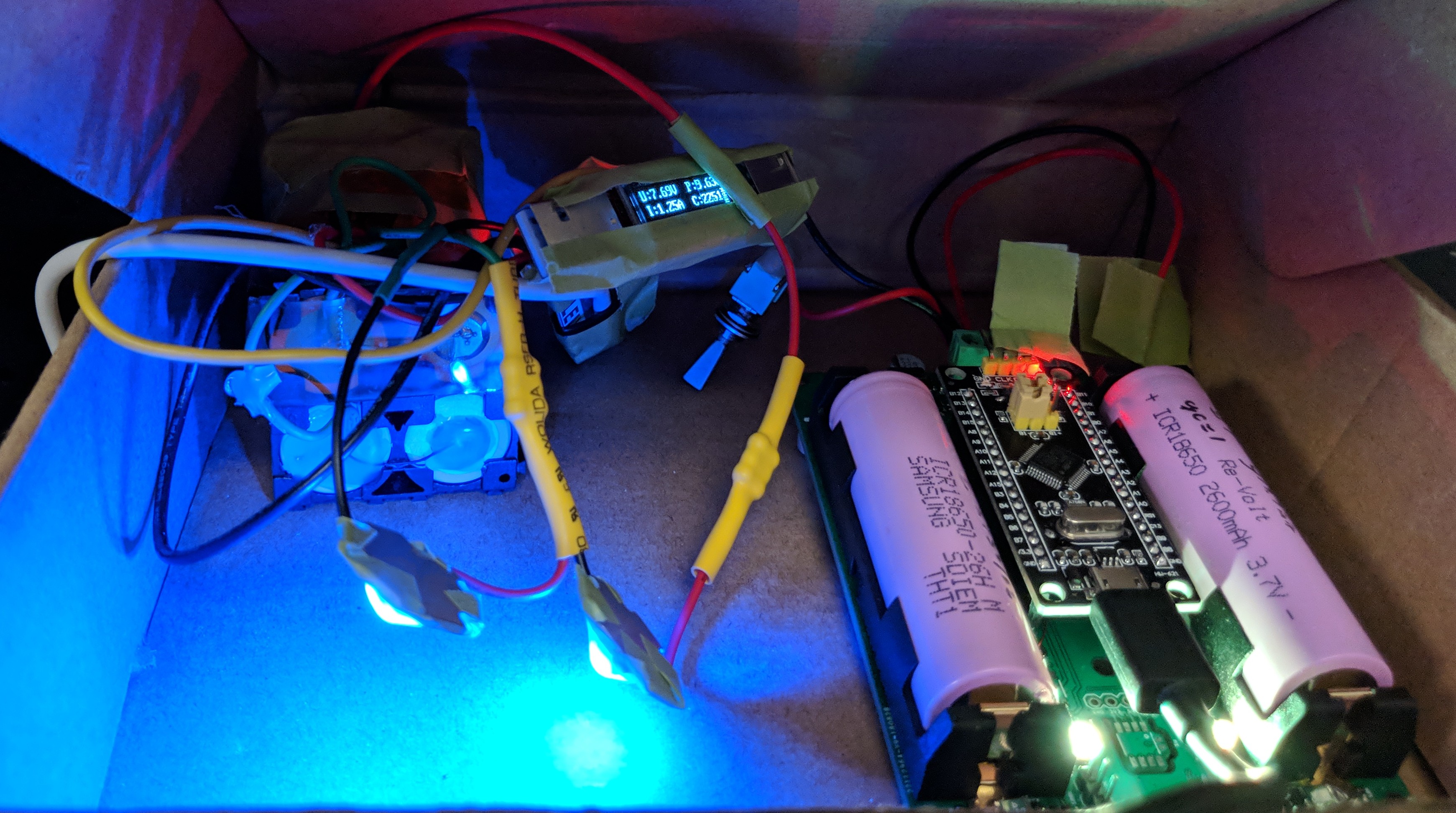
CCR v1 prototype in regenerative configuration
...
