Ryobi40V: Difference between revisions
Jump to navigation
Jump to search
No edit summary |
|||
| Line 6: | Line 6: | ||
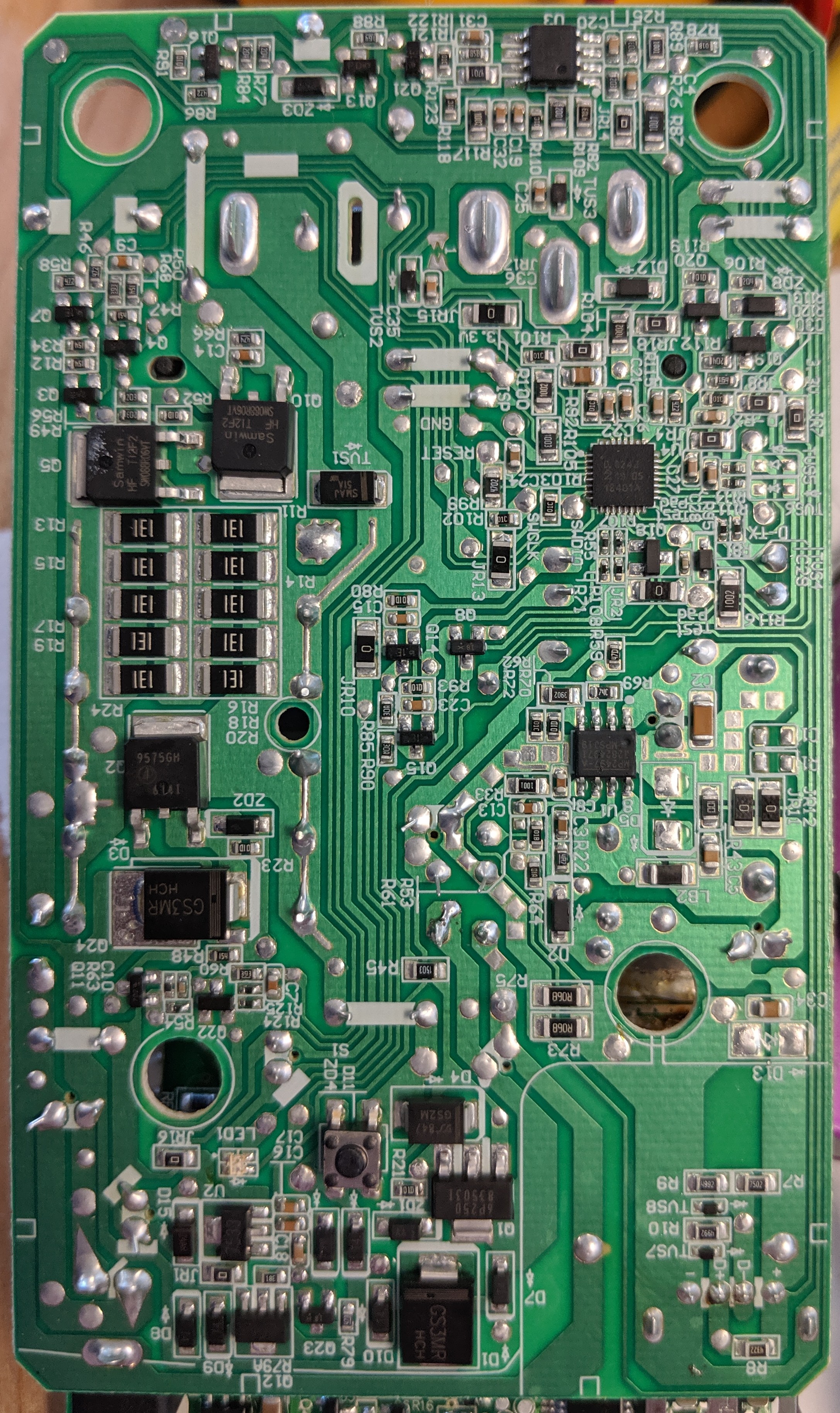
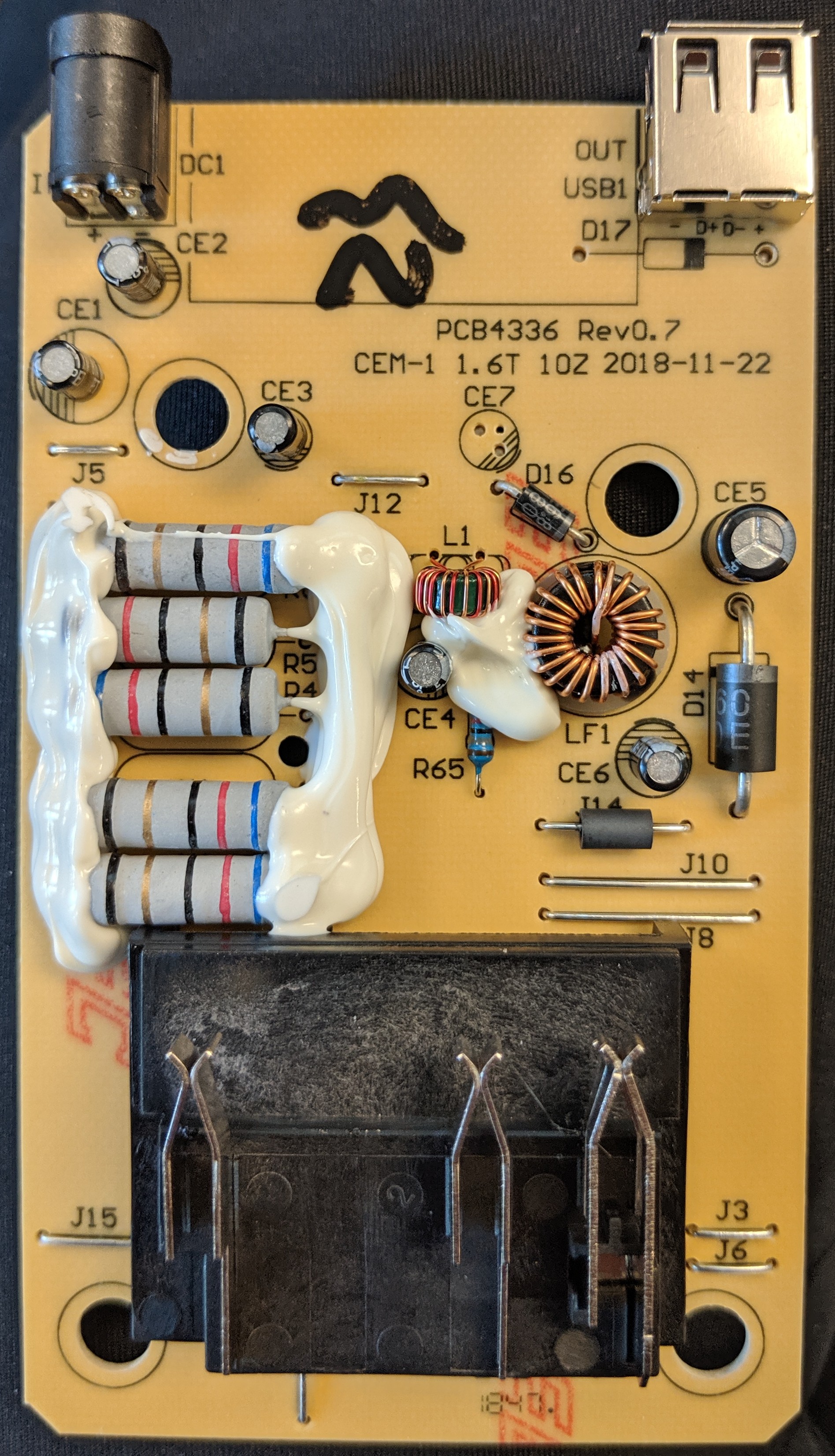
[[File:Ryobi_40VChg_PCB_Bot.jpg|thumb|center|400px|PCB bottom side.]] | [[File:Ryobi_40VChg_PCB_Bot.jpg|thumb|center|400px|PCB bottom side.]] | ||
The wall wart adapter is a 42V 1.5A rated switching converter, listed at 84W max from AC (though output is max 63W). The wall wart does the necessary CC/CV current limiting, with a ~44. | The wall wart adapter is a 42V 1.5A rated switching converter, listed at 84W max from AC (though output is max 63W). The wall wart does the necessary CC/CV current limiting, with a ~44.15V open circuit voltage output when no battery is connected. Output is switched to the battery though a MOSFET. | ||
Charging Sequence: | Charging Sequence: | ||
Revision as of 00:21, 13 August 2019
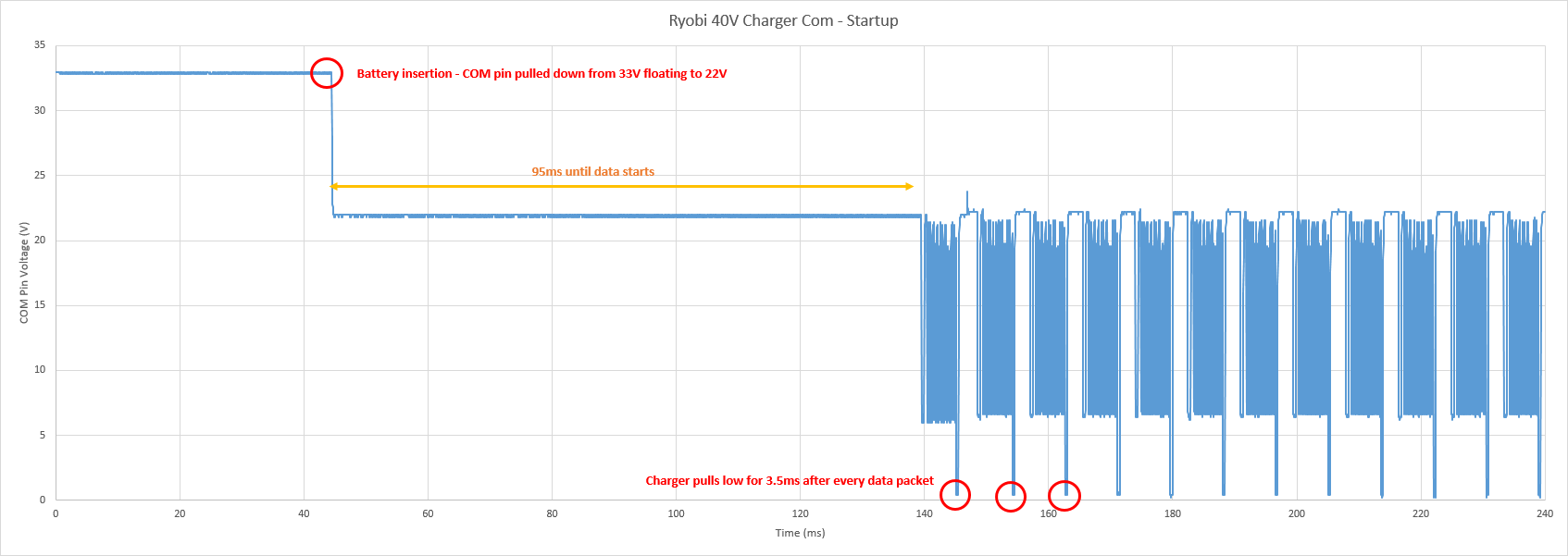
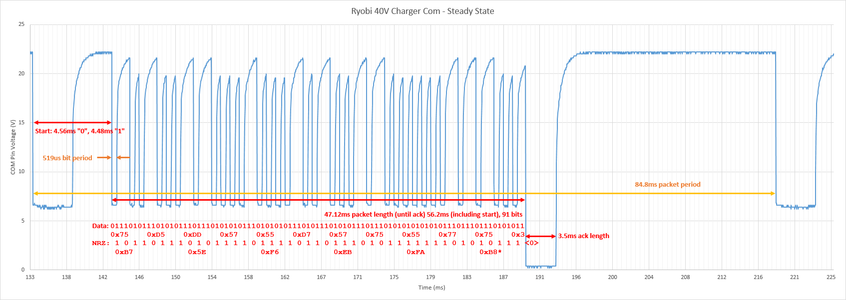
This is a basic analysis of how a Ryobi 40V smart charger (model number OP403) communicates with the battery's BMS to enable the charging FET.
Electronics
Pictures of the charger PCB are below:
The wall wart adapter is a 42V 1.5A rated switching converter, listed at 84W max from AC (though output is max 63W). The wall wart does the necessary CC/CV current limiting, with a ~44.15V open circuit voltage output when no battery is connected. Output is switched to the battery though a MOSFET.
Charging Sequence:
Data detail:
The charger includes a 5V 1.5A buck based on a MP2487 (4.5-55V in, 220mOhm PFET, 1.5A max). The sticker claims 5V 2.1A output.


