Misc Projects
This is a list of breakout boards and smaller miscellaneous projects that have been created. All of the following designs are open-source, and all are welcome to modify and use these designs as they please.
MS5534 Breakout
This is a breakout board for the MS5534 digital pressure sensor. It includes the sensor itself, a 22uF Tantalum decoupling capacitor, and circuitry to generate a 32kHz reference clock for the chip's ADC and supporting circuitry.
- Ms5534 eagle layout.jpg
Eagle board layout for the MS5534 Breakout.
Files: http://www.rev0proto.com/files/MiscProjects/ms5534_v10.zip
Clock generation circuit is incorrect, new revision needs to be made.
XBee Pro XSC Breakout
This is a breakout board for the XBee Pro XSC 900MHz radio transceiver. It includes a 300mA 3.3V LDO for powering the device from USB, and all XBee pins are broken out to standard 0.1" headers. The design is similar to the Parallax XBee USB Adapter Board, though specialized for the XBee Pro XSC. Credit goes to Justin Jordan for the original schematic made in PCB Artist.
- Xbee breakout eagle layout.jpg
This is the Eagle layout for the XBee Pro XSC USB breakout board.
Files: http://www.rev0proto.com/files/MiscProjects/xbee_usb_breakout_v10.zip
MCP2200 Breakout
This is a breakout board for the MCP2200 USB-to-UART bridge IC. It includes the chip, a mini-B USB connector, and four status LEDs. The IC is provided a 12MHz SMD crystal on the underside of the board, and all pins are accessible on the header.
- Mcp2200 bare-boards.jpg
A set of MCP2200 breakout boards pre-soldering.
- Mcp2200 populated bottom.jpg
The bottom side of a populated MCP2200 breakout board.
- Mcp2200 populated top.jpg
The top side of a powered up MCP2200 breakout board.
Files: http://www.rev0proto.com/files/MiscProjects/MCP2200_v11.zip
ADC-10-4 Directional Coupler Breakout
This is a breakout board for the ADC-10-4 directional coupler from Mini-Circuits. It includes the device and SMA connectors for all four ports of the device, as well as pads for soldering on a 50 ohm terminator for the terminated port.
The device's internal construction is of the type detailed on this page: http://michaelgellis.tripod.com/direct.html The schematic for the internal construction is shown below.
Testing was performed on the device using an Anritsu MS4622B vector network analyzer using the configurations shown below. The results are summarized in the two graphs below, which show that the device compares well to and exceeds the manufacturer specifications, with the exception of insertion loss, coupling at higher frequencies, and the CPL port return loss.
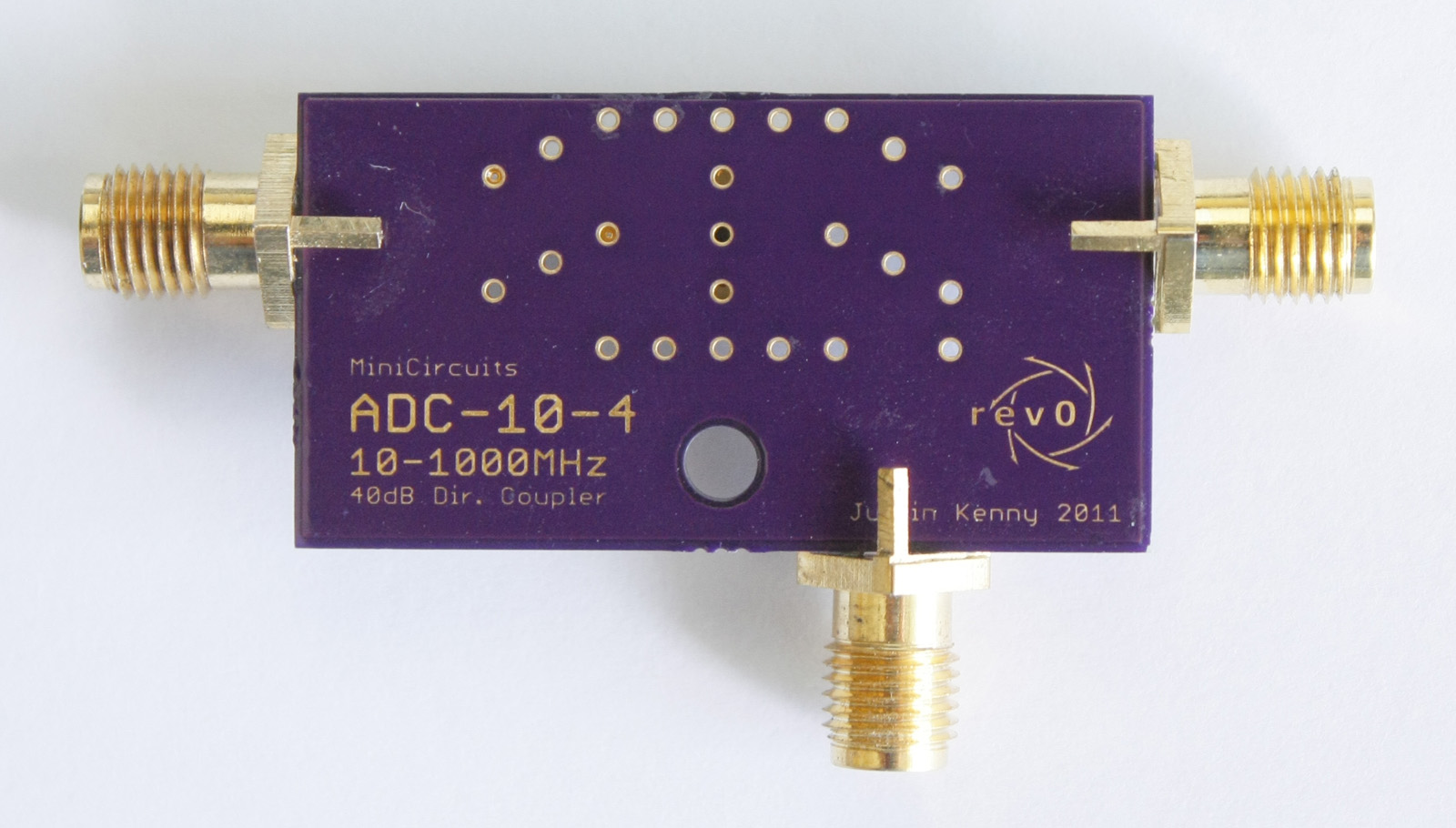
Top side of the ADC-10-4 breakout.
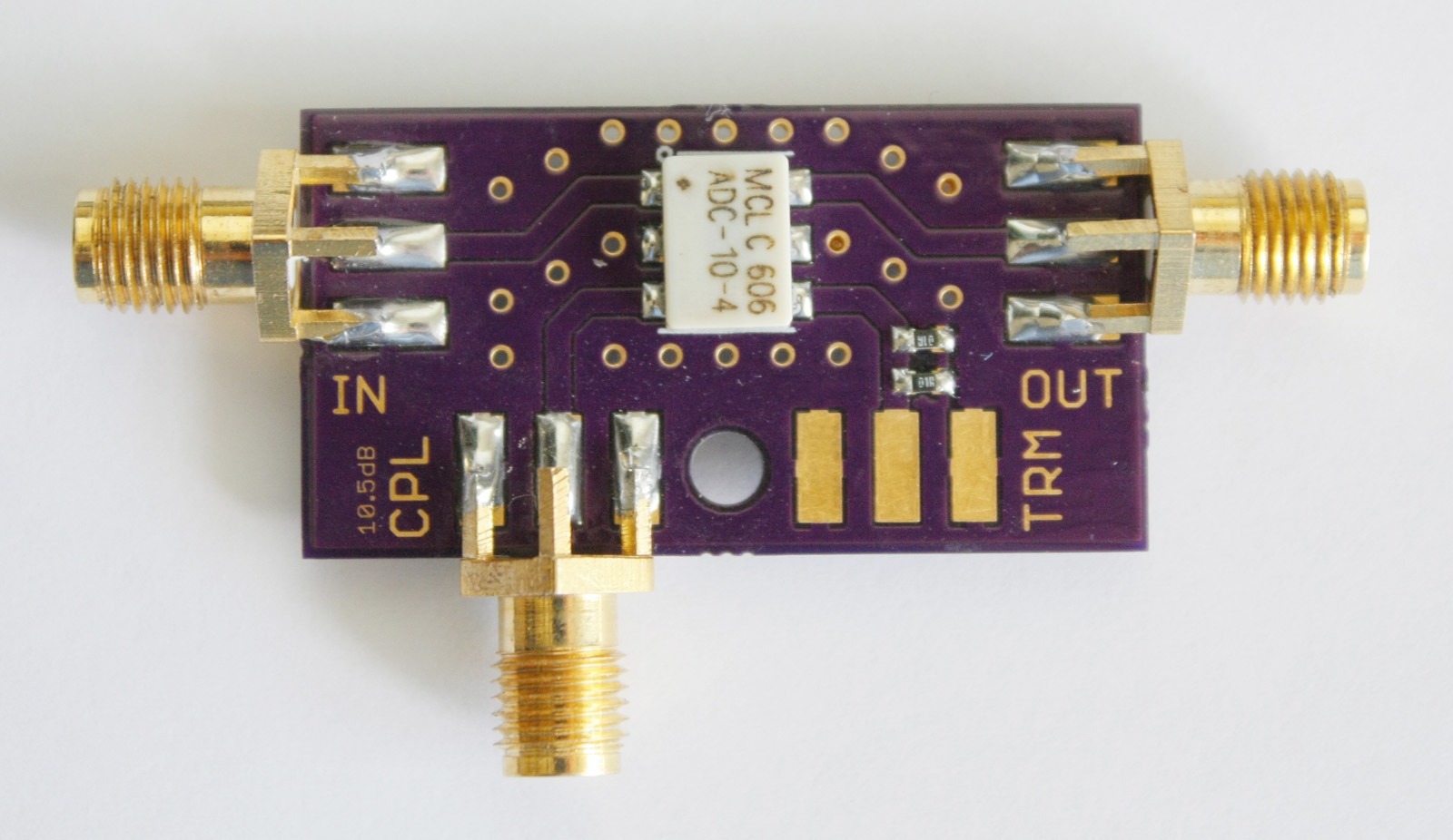
Bottom side of the ADC-10-4 breakout.
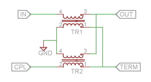
Schematic of the internal construction of the ADC-10-4.
- ADC-10-4 Measurement Setup.png
The measurement configurations for determining return loss, insertion loss, directivity, and coupling.
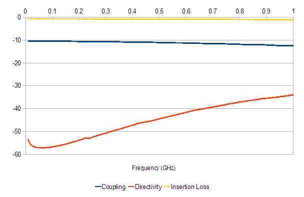
Coupling, directivity, and insertion loss of the ADC-10-4.
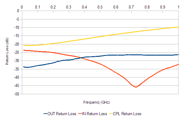
Return loss of all three ports of the ADC-10-4.


Board Files: http://www.rev0proto.com/files/MiscProjects/dircoupler_v10.zip
Test Data: http://www.rev0proto.com/files/MiscProjects/ADC-10-4.zip