CCR: Difference between revisions
| Line 156: | Line 156: | ||
===CCR Mini 360=== | ===CCR Mini 360=== | ||
This was an investigation to use an off the shelf synchronous buck converter module to produce a regenerative charger/discharger by overriding the module's feedback node, injecting a voltage signal in to bias the module to higher or lower output voltage/current, which when biased lower than the attached battery's voltage would act as a synchronous boost converter, charging the buffer pack. This prototype was successful in concept but had poor regulation and performance, able to manage ~ | This was an investigation to use an off the shelf synchronous buck converter module to produce a regenerative charger/discharger by overriding the module's feedback node, injecting a voltage signal in to bias the module to higher or lower output voltage/current, which when biased lower than the attached battery's voltage would act as a synchronous boost converter, charging the buffer pack. This prototype was successful in concept but had poor regulation and performance, able to manage ~0.8-0.9A in discharge and ~1.3-1.5A in charge. | ||
===CCR Dev + Buck=== | ===CCR Dev + Buck=== | ||
Revision as of 14:39, 14 January 2019
This is a project to create a regenerative capable dual slot 18650 Li-* battery tester, which when used in conjunction with computer software or an additional ESP8266 module (yet to be implemented) can also graph the data in real time to Thingspeak or InfluxDB/Grafana for analysis.

List of Features
Version 1 - Regenerative Only
- Voltage Range (Charge): 0-4.35V
- Max Current (Charge): 1.5A
- Max Current (Discharge): 1.5A
- Sample Rate: 1 Hz (Reporting rate), 2 kHz (Loop/Integration rate)
- Efficiency: 84% (Buck/charge mode, average, 1.5A output), 82.2% (Boost/discharge mode, average, 1.5A output)
Version 2 - Regenerative Mode
High Power Variant
- Charge: Up to 5A (tbd)
- Discharge: Up to 5A (tbd)
Low Power Variant
- Charge: Up to 1.5A
- Discharge: Up to 1.5A
Version 2 - Non-regenerative Mode
High Power Variant
- Charge: Up to 5A (tbd)
- Discharge: Up to 5A (single channel), 3A (dual channel)
Low Power Variant
- Charge: Up to 1.5A
- Discharge: Up to 3A
Output Format
State List:
- 0. Battery Disconnected (Unused)
- 1. Battery Discharge
- Voltage < 2.75V?
- 2. Battery Disconnected
- Wait 5 minutes
- 3. Battery Charge
- Current < 50mA?
- 4. Battery Disconnect
- 5. Wait 1 minute
- 6. Measure IR
- 7. Measure IR
- Wait 10 seconds
- 8. Parking
Message Type List:
- 0. Cell 1 periodic status
- 1. Cell 1 end of discharge stats
- 2. Cell 1 end of charge stats
- 3. Cell 1 IR debug
- 4. Buffer pack voltage/system status
- 5. Cell 2 periodic status
- 6. Cell 2 end of discharge stats
- 7. Cell 2 end of charge stats
- 8. Cell 2 IR debug
| Message Type (Periodic Status) | Battery Voltage (mV) | Battery Current (mA) | Capacity (mAH) | Capacity (mWH) | Temperature (C) | State |
| 0 | 3752 | 1499 | 648 | 2565 | 23.6 | 1 |
| 5 | 3942 | -1454 | 980 | 3658 | 25.8 | 3 |
| Message Type (End of Discharge) | Battery Voltage (mV) | Battery Internal Resistance (mOhm) | Capacity (mAH) | Capacity (mWH) | Temperature (C) | State |
| 1 | 3015 | 149.3 | 648 | 2565 | 23.6 | 2 |
| 6 | 2975 | 45.2 | 2012 | 7518 | 27.3 | 2 |
| Message Type (End of Charge) | Battery Voltage (mV) | Battery Internal Resistance (mOhm) | Capacity (mAH) | Capacity (mWH) | Temperature (C) | State |
| 2 | 4109 | 105.4 | 980 | 3658 | 25.8 | 7 |
| 7 | 4103 | 48.4 | 1780 | 6507 | 28.4 | 7 |
Development
Breadboard Prototype
Early investigation of the concept started with determining the maximum PWM frequency and resolution the STM32F103 could produce, and how to size the inductor and capacitor accordingly to produce a 1.5A output with good current regulation. The best compromise of frequency and resolution was selected to be 360kHz with 200 steps. This was simulated in LTSpiceIV to size the inductor and capacitor for the buck, chosen to be 33uH with 440uF of output capacitance. The buck circuit was assembled on a breadboard but ultimately did not work due to the high parasitics at the frequency used (360kHz).
COTS Cycler
For cycler software development (excluding the closed loop feedback and PWM, i.e. state machine and interface) a second prototype was built using a CC-CV 3A buck converter module and Re:load v2 constant current load connected to a Maple Mini and additional temperature sensing and current/voltage sensing circuitry.
CCR v1.0
CCR Dev (Resistive Load)
CCR Mini 360
This was an investigation to use an off the shelf synchronous buck converter module to produce a regenerative charger/discharger by overriding the module's feedback node, injecting a voltage signal in to bias the module to higher or lower output voltage/current, which when biased lower than the attached battery's voltage would act as a synchronous boost converter, charging the buffer pack. This prototype was successful in concept but had poor regulation and performance, able to manage ~0.8-0.9A in discharge and ~1.3-1.5A in charge.
CCR Dev + Buck
CCR Dev + 6A Buck
Heatsink Sizing
The cooling solution for the 2 MOSFETs that make up the discharging circuit is a 100x40x20mm aluminum extruded heatsink with 11 fins, and a 5V 40x40x20mm fan. Results are as follows (tested at ~21 C ambient):
- 4A 4.2V (16.8W) (2A x2) - 65 C max on FET body, approx. 71.3 C Tj
- 5A 4.2V (21W) (2.5A x2) - 75 C max on FET body, approx. 82.9 C Tj
- 6A 4.2V (25.2W) (3A x2) - 84 C max on FET body, approx. 93.5 C Tj
- 7A 4.2V (29.4W) (3.5A x2) - 93 C max on FET body, approx. 104 C Tj
- 4A 4.2V (16.8W) (4A x1) - 79 C max on FET body, approx. 91.6 C Tj
- 5A 4.2V (21W) (5A x1) - 93 C max on FET body, approx. 108.8 C Tj
Electronics
Buck Converter (Charger)
...
Boost Converter (Discharger, regenerative)
...
CCR v1 Performance Evaluation

Constant Current Load (v2 Discharger, resistive)
...
Microcontroller
The CCR uses an STM32F103C8 microcontroller in the form of a "blue pill" board, which includes crystals, header pins, USB plug, and other supporting circuitry, and allows for the MCU to be swapped out in case of damage.
Hardware Revisions
Revision 1.0
This is the first revision of the CCR, which only natively supports regenerative discharging mode.
Errata:
- Pin A12 was used for the P-channel MOSFET control on cell 2, which is not usable for this function (pin is natively used as USB D+).
- ...
Revision 2.0
This is the second revision of the CCR, which supports regenerative discharging mode (optional) as well as constant current discharging mode, and increased current capability of up to 3A in charge, and 5A (single channel)/3A (dual channel) in discharge.
Change List:
- ...
Errata:
- ...
PCB Files
Here is the Eagle schematic file for the CCR v1.0: http://rev0proto.com/files/tbd.sch Here is the Eagle board file for the CCR v1.0: http://rev0proto.com/files/tbd.brd
Enclosure
The enclosure for the CCR v2.0 was created in Fusion 360 and is made up of x pieces which can be 3D printed and assembled with M3 screws.
Here are the Fusion 360 files for the CCR v2.0 enclosure: http://rev0proto.com/files/tbd.zip
Code
Full source code for the project can be found here: http://rev0proto.com/files/x.zip
Videos
<HTML5video type="youtube" width="400" height="300" autoplay="false">1SHY4jAfTcM</HTML5video>
Photos
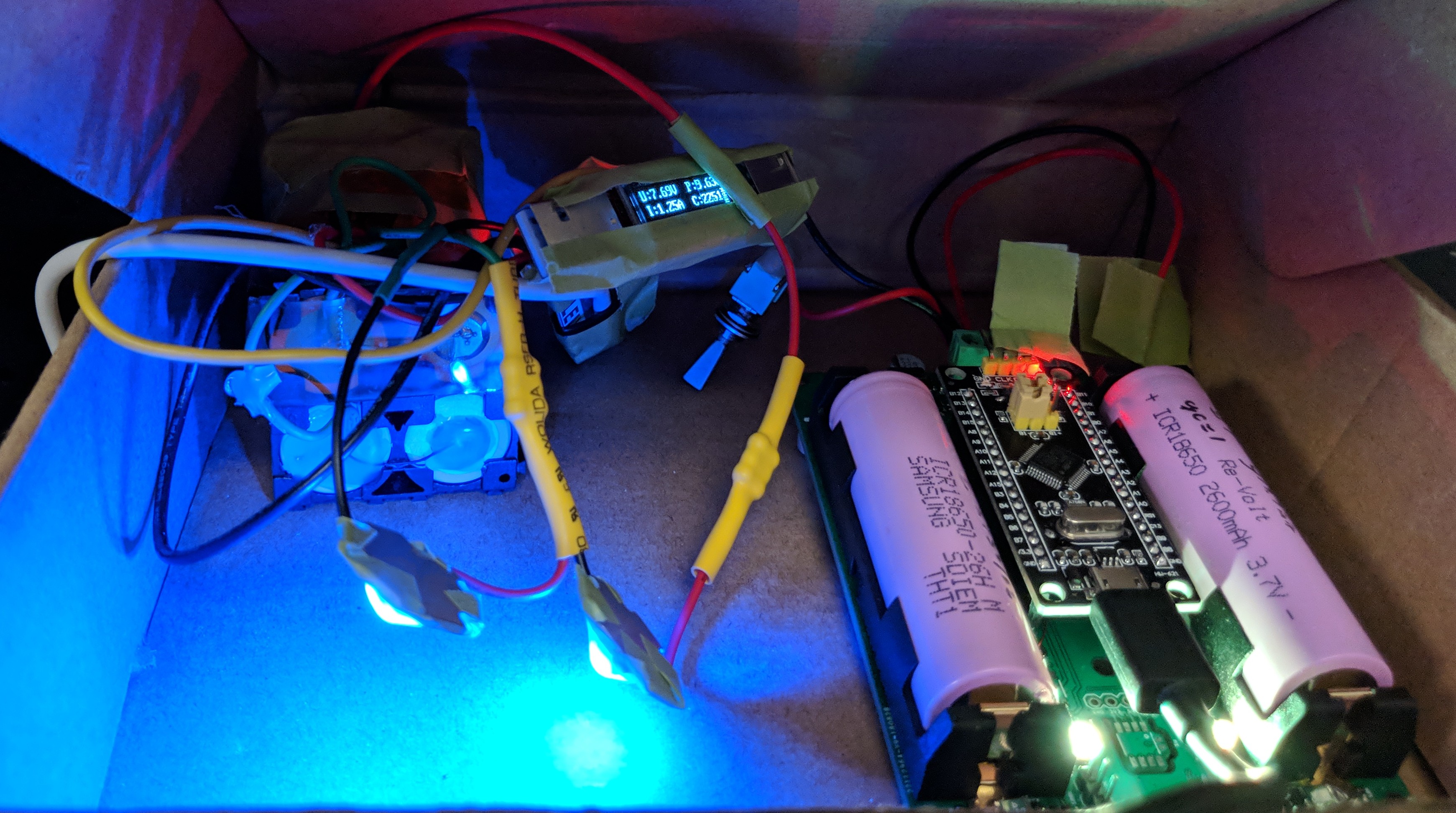
CCR v1 prototype in regenerative configuration
...
Total Project Cost
| Component | Cost | Source |
| Enclosure (Top) | $19.03 | Shapeways |
| Enclosure (Bottom) | $22.33 | Shapeways |
| Enclosure (Buttons/Switch/Cover/Shipping) | $20.65 | Shapeways 123 |
| PCB | $8.40 | OSH Park |
| Geiger Tube | $7.44 | eBay |
| Battery | $4.04 | HobbyKing |
| Components | $25.86 | Digi-Key |
| Total Price | $107.75 |