CCR: Difference between revisions
| Line 145: | Line 145: | ||
[[File:GC-D_1000_Schematic_v1.1.png|thumb|right|The complete system schematic for the GC-D 1000 Geiger counter.]] | [[File:GC-D_1000_Schematic_v1.1.png|thumb|right|The complete system schematic for the GC-D 1000 Geiger counter.]] | ||
=== | ===Buck Converter (Charger)=== | ||
... | |||
===Microcontroller | ===Boost Converter (Discharger, regenerative)=== | ||
... | |||
===Constant Current Load (v2 Discharger, resistive)=== | |||
... | |||
===Microcontroller=== | |||
[[File:GC-D_1000_Board_v1.1.png|thumb|right|The PCB layout (top: red, bottom: blue) for the GC-D 1000.]] | [[File:GC-D_1000_Board_v1.1.png|thumb|right|The PCB layout (top: red, bottom: blue) for the GC-D 1000.]] | ||
The CCR uses an STM32F103C8 microcontroller in the form of a "blue pill" board, which includes crystals, header pins, USB plug, and other supporting circuitry, and allows for the MCU to be swapped out in case of damage. | |||
===Hardware Revisions=== | ===Hardware Revisions=== | ||
====Revision 1.0==== | ====Revision 1.0==== | ||
This is the first revision of the | This is the first revision of the CCR, which only natively supports regenerative discharging mode. | ||
''' | '''Errata:''' | ||
* | * Pin A12 was used for the P-channel MOSFET control on cell 2, which is not usable for this function (pin is natively used as USB D+). | ||
* ... | |||
====Revision | ====Revision 2.0==== | ||
This is the | This is the second revision of the CCR, which supports regenerative discharging mode (optional) as well as constant current discharging mode, and increased current capability of up to 3A in charge, and 5A (single channel)/3A (dual channel) in discharge. | ||
''' | '''Change List:''' | ||
* | * ... | ||
''' | '''Errata:''' | ||
* | * ... | ||
====PCB Files==== | ====PCB Files==== | ||
Here is the Eagle schematic file for the | Here is the Eagle schematic file for the CCR v1.0: http://rev0proto.com/files/tbd.sch | ||
Here is the Eagle board file for the | Here is the Eagle board file for the CCR v1.0: http://rev0proto.com/files/tbd.brd | ||
==Enclosure== | ==Enclosure== | ||
Revision as of 20:46, 10 January 2019
This is a project to create a fully functional, production-ready digital Geiger counter. It builds on the features of the GC-D 100, including the change to a graphic LCD, USB rechargable LiPo battery, USB upgradable firmware, significantly lower power usage, and the move to a lower cost and more common Geiger tube, all at around 80% of the cost of the original.

List of Features
Version 1 - Regenerative Only
- Voltage Range (Charge): 0-4.35V
- Max Current (Charge): 1.5A
- Max Current (Discharge): 1.5A
- Sample Rate: 1 Hz (Reporting rate), 2 kHz (Loop/Integration rate)
- Efficiency: 84% (Buck/charge mode, average, 1.5A output), 82.2% (Boost/discharge mode, average, 1.5A output)
Version 2 - Regenerative Mode
Version 2 - Non-regenerative Mode
Output Format
State List:
- 0. Battery Disconnected (Unused)
- 1. Battery Discharge
- Voltage < 2.75V?
- 2. Battery Disconnected
- Wait 5 minutes
- 3. Battery Charge
- Current < 50mA?
- 4. Battery Disconnect
- 5. Wait 1 minute
- 6. Measure IR
- 7. Measure IR
- Wait 10 seconds
- 8. Parking
Message Type List:
- 0. Cell 1 periodic status
- 1. Cell 1 end of discharge stats
- 2. Cell 1 end of charge stats
- 3. Cell 1 IR debug
- 4. Buffer pack voltage/system status
- 5. Cell 2 periodic status
- 6. Cell 2 end of discharge stats
- 7. Cell 2 end of charge stats
- 8. Cell 2 IR debug
| Message Type (Periodic Status) | Battery Voltage (mV) | Battery Current (mA) | Capacity (mAH) | Capacity (mWH) | Temperature (C) | State |
| 0 | 3752 | 1499 | 648 | 2565 | 23.6 | 1 |
| 5 | 3942 | -1454 | 980 | 3658 | 25.8 | 3 |
| Message Type (End of Discharge) | Battery Voltage (mV) | Battery Internal Resistance (mOhm) | Capacity (mAH) | Capacity (mWH) | Temperature (C) | State |
| 1 | 3015 | 149.3 | 648 | 2565 | 23.6 | 2 |
| 6 | 2975 | 45.2 | 2012 | 7518 | 27.3 | 2 |
| Message Type (End of Charge) | Battery Voltage (mV) | Battery Internal Resistance (mOhm) | Capacity (mAH) | Capacity (mWH) | Temperature (C) | State |
| 2 | 4109 | 105.4 | 980 | 3658 | 25.8 | 7 |
| 7 | 4103 | 48.4 | 1780 | 6507 | 28.4 | 7 |
Heatsink Sizing
The cooling solution for the 2 MOSFETs that make up the discharging circuit is a 100x40x20mm aluminum extruded heatsink with 11 fins, and a 5V 40x40x20mm fan. Results are as follows (tested at ~21 C ambient):
- 4A 4.2V (16.8W) (2A x2) - 65 C max on FET body, approx. 71.3 C Tj
- 5A 4.2V (21W) (2.5A x2) - 75 C max on FET body, approx. 82.9 C Tj
- 6A 4.2V (25.2W) (3A x2) - 84 C max on FET body, approx. 93.5 C Tj
- 7A 4.2V (29.4W) (3.5A x2) - 93 C max on FET body, approx. 104 C Tj
- 4A 4.2V (16.8W) (4A x1) - 79 C max on FET body, approx. 91.6 C Tj
- 5A 4.2V (21W) (5A x1) - 93 C max on FET body, approx. 108.8 C Tj
Electronics

Buck Converter (Charger)
...
Boost Converter (Discharger, regenerative)
...
Constant Current Load (v2 Discharger, resistive)
...
Microcontroller

The CCR uses an STM32F103C8 microcontroller in the form of a "blue pill" board, which includes crystals, header pins, USB plug, and other supporting circuitry, and allows for the MCU to be swapped out in case of damage.
Hardware Revisions
Revision 1.0
This is the first revision of the CCR, which only natively supports regenerative discharging mode.
Errata:
- Pin A12 was used for the P-channel MOSFET control on cell 2, which is not usable for this function (pin is natively used as USB D+).
- ...
Revision 2.0
This is the second revision of the CCR, which supports regenerative discharging mode (optional) as well as constant current discharging mode, and increased current capability of up to 3A in charge, and 5A (single channel)/3A (dual channel) in discharge.
Change List:
- ...
Errata:
- ...
PCB Files
Here is the Eagle schematic file for the CCR v1.0: http://rev0proto.com/files/tbd.sch Here is the Eagle board file for the CCR v1.0: http://rev0proto.com/files/tbd.brd
Enclosure
The enclosure for the GC-D 1000 was created with Autodesk Inventor 3D CAD software, and manufactured using rapid prototyping through Shapeways. Dimensions for all major parts and the PCB were taken from their respective datasheets or by using a digital caliper, and 3D representations were made in Inventor. Then the basic shape for the enclosure was devised, and it was created with the constraints given by the parts needed. The enclosure is made of 5 separate pieces, which are assembled by snapping them together.
Here are the Autodesk Inventor files for the GC-D 1000: http://rev0proto.com/files/GC-D_1000_Model.zip
Code
Full source code for the project can be found here: http://rev0proto.com/files/gc-d_1000.zip
Comparison to GC-D 100
The first change I wanted to make on the GC-D 100 was the battery. With my previous experience from the rev0Trac VTx, I decided to use a single-cell 1000mAH LiPo for the GC-D 1000. The primary constraint for the batteries for the GC-D 100 was the voltage needed for the step-up converter. By optimizing the boost converter design, both through simulation and breadboard prototyping, I was able to design a circuit that would operate down to the LiPo minimum of 3.0V (the boost converter can operate down to 2.6V in practice). This allowed the device to operate on a single cell, eliminating the challenges of balancing and charging a dual-cell LiPo. The voltage for the ATtiny10 microcontroller is still provided by a 5V synchronous boost converter, and is needed to operate the MOSFET efficiently (high enough voltage to operate in saturation).
The high voltage circuitry in the GC-D 100 was scattered throughout the PCB layout, a potential danger when operating the device without the case, and a potential danger to the low-voltage circuitry surrounding it. The GC-D 1000 was routed such that the high voltage circuitry is spatially isolated in the bottom section of the PCB, clearly marked by silkscreen. I chose not to optically isolate the two sections due to the low selection of high-speed opto-isolators and the packages they are available in. The boost converter is operated by an independent microcontroller, freeing up cycles and adding an extra layer of isolation to the application MCU. The Geiger tube output is fed through a Schmitt inverter to clean up the signal and also provide isolation from the Geiger tube.
Drawing again from my experience with the rev0Trac VTx, the GC-D 1000 uses a Nokia 5110 graphic LCD. In addition to giving more freedom with displaying information, it is thinner, cheaper, and much lower power than the 8x2 character LCD used in the GC-D 100.
This device was designed on a smaller timeline (~6 weeks) than the original and optimized for cost and manufacturability, thus some of the more exotic features, such as location logging are left out. This device nevertheless uses a more powerful microcontroller, programmable over USB, and has much greater potential for expansion.
Videos
<HTML5video type="youtube" width="400" height="300" autoplay="false">1SHY4jAfTcM</HTML5video> <HTML5video type="youtube" width="400" height="300" autoplay="false">nnFNTOPaNV0</HTML5video>
Photos
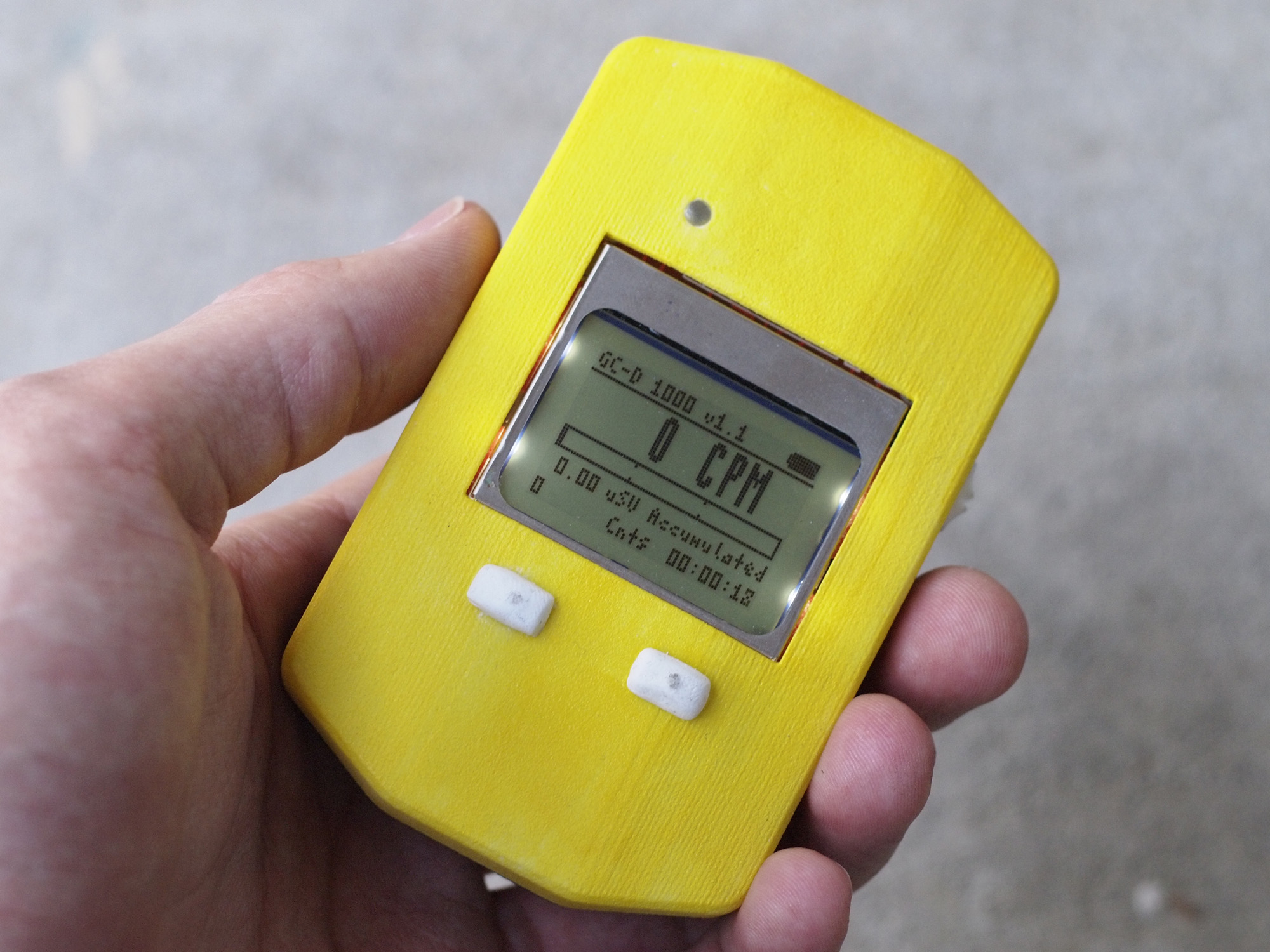
GC-D 1000 Handheld
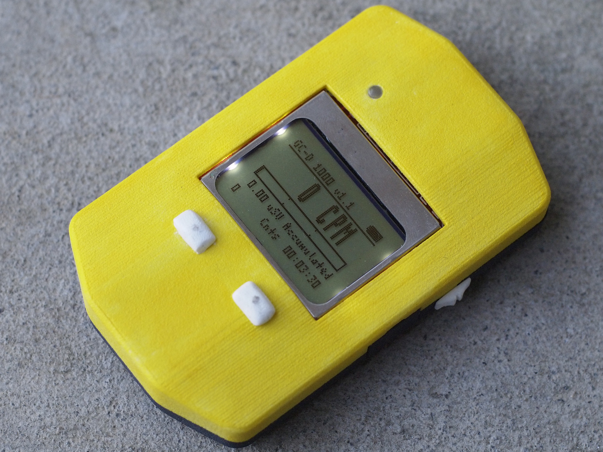
Top view of the GC-D 1000
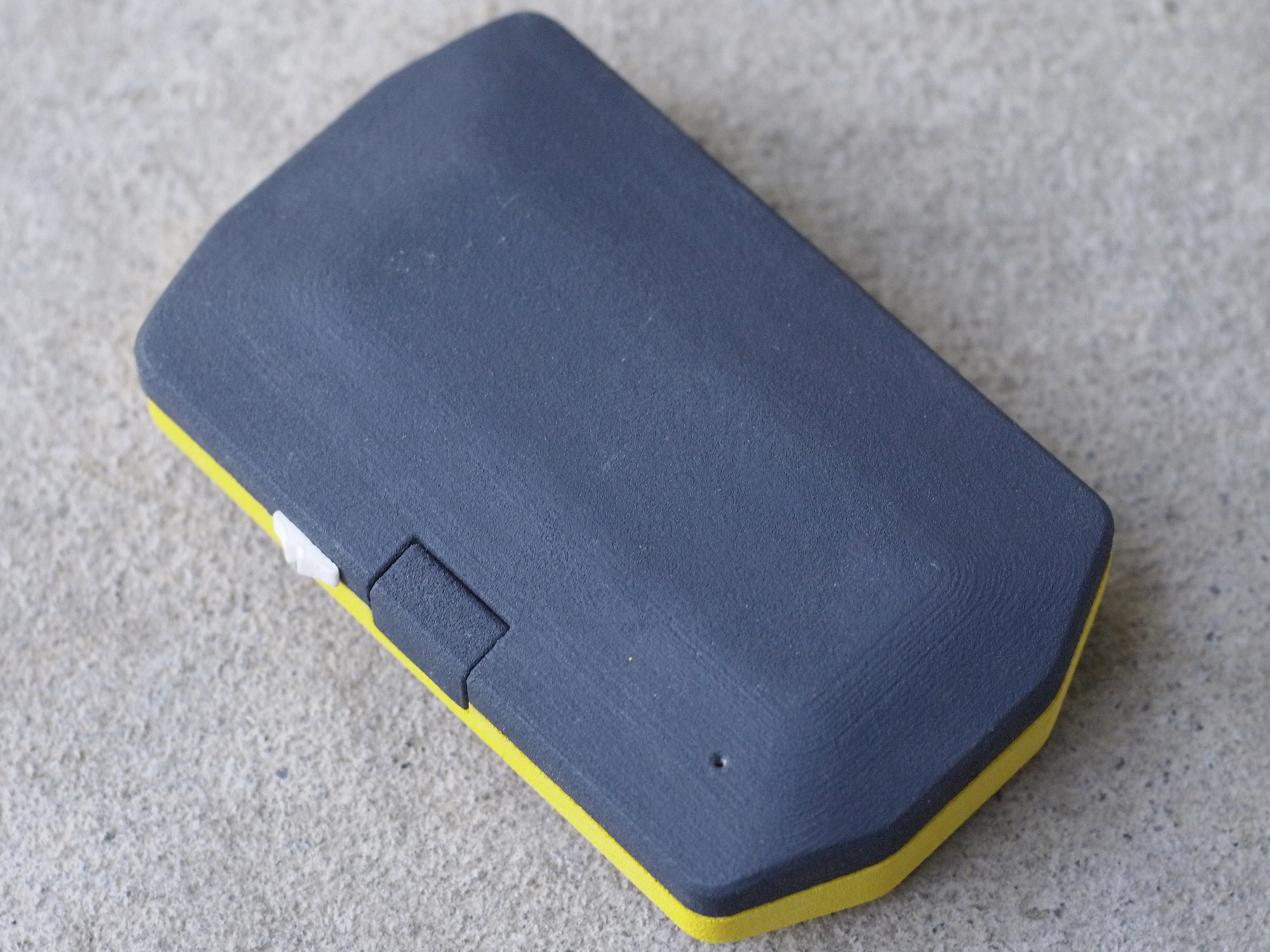
Bottom view of the GC-D 1000
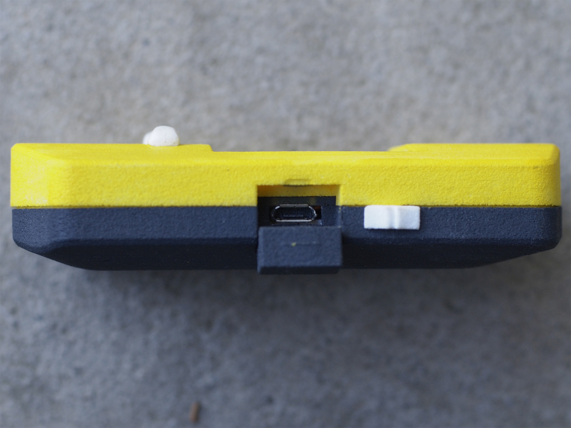
Side view of the GC-D 1000


Total Project Cost
| Component | Cost | Source |
| Enclosure (Top) | $19.03 | Shapeways |
| Enclosure (Bottom) | $22.33 | Shapeways |
| Enclosure (Buttons/Switch/Cover/Shipping) | $20.65 | Shapeways 123 |
| PCB | $8.40 | OSH Park |
| Geiger Tube | $7.44 | eBay |
| Battery | $4.04 | HobbyKing |
| Components | $25.86 | Digi-Key |
| Total Price | $107.75 |