SA LO1
This page describes the 1st Local Oscillator for the DIY Spectrum Analyzer.
Summary
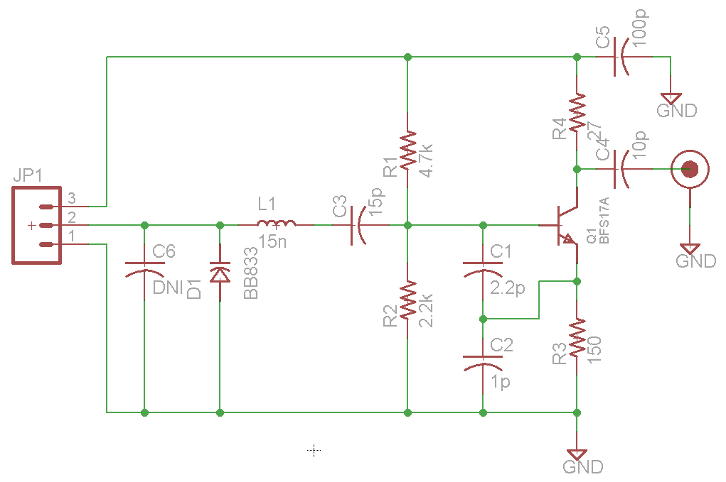
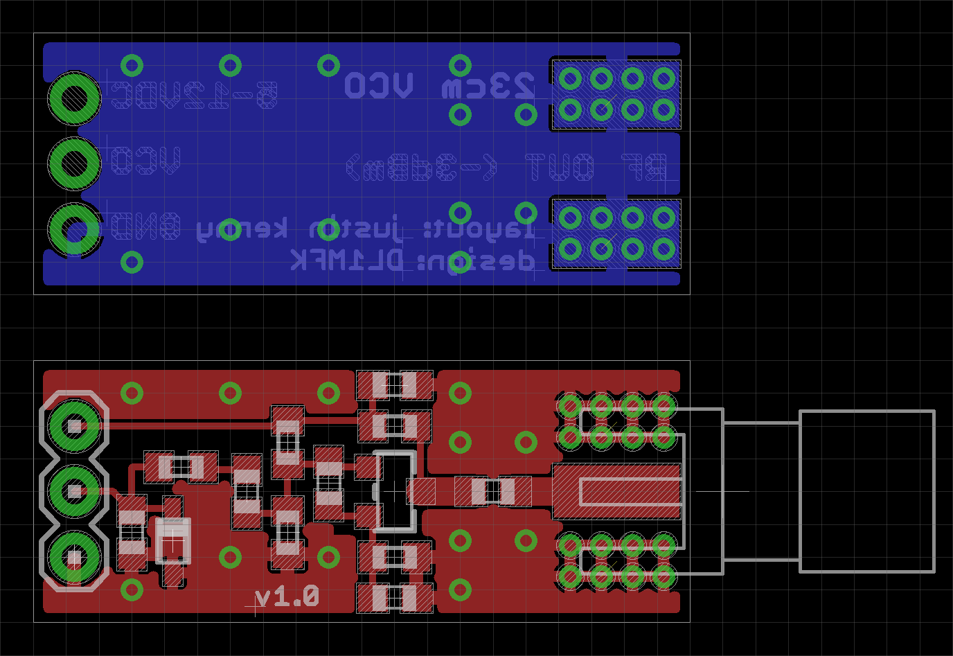
The 1st LO is based around the ADF4350 2.2-4.4GHz MAX2870 3-6GHz PLL with integrated VCO. The loop filter is designed to 54.7kHz with 61.4° phase margin, optimized for the lowest phase noise across offsets of 100Hz-10MHz as simulated in ADIsimPLL. The PCB includes a 10 MHz TCXO reference oscillator, and has voltage regulation and a MSP430G2553 microcontroller to provide basic control via serial interface.
Register Configuration
A worksheet was created to translate register settings into the 32-bit register words for hard-coding into the microcontroller. The initial settings can be found below.
Testing
- 7.31.2013: The first three components were assembled (ADF4350, ADP124, AP1113) via hot-air reflow. A short was discovered between power (3.3V) and ground. Review of the PCB layout indicated this was due to the power and ground layers being shorted together internal to the PCB (verified on other blank PCBs). This was caused by the internal layers being an older revision (with U1 having 4 ground vias instead of the current 9). The first three components were then removed.
- 8.1.2013: The internal layer was cut from the bottom side of the board to remove the short. A piece of copper tape was then soldered to bridge ground on the bottom layer (which was cut in order to get to the power layer).
- 8.2.2013: The board was assembled and powered. The power supplies were first verified, followed by the microcontroller and SPI. The ADF4350 was programmed to output a high level on LD to ensure SPI was being read correctly. There was no RF output observed.
- 8.4.2013: The voltage levels on the ADF4350 were checked on each pin to ensure no shorts. Vp (charge pump supply) was found to be disconnected. This was tied externally to AVDD. Output was then observed at the correct frequency. The power on reset resistor/capacitor was omitted in the schematic, preventing the MCU from powering up properly.
- 8.5.2013: The phase noise was measured at 442.5 MHz at offsets of 100, 1k, and 10k at the following: -78, -88, -94dBc, with a carrier power of 0dBm.
- 8.7.2013: The microcontroller was programmed to accept serial commands to set the divider, integer, and fractional settings for the ADF4350.
- 8.8.2013: The output power of the RF Out A+ port was measured at 24 frequencies with results shown below. The nominal output power from 150-1000 MHz is 0dBm.
| Frequency (MHz) | Power (dBm) |
| 150 | -0.06 |
| 200 | -0.02 |
| 250 | -0.03 |
| 300 | -0.07 |
| 350 | -0.06 |
| 400 | 0.03 |
| 450 | 0.04 |
| 500 | 0.02 |
| 550 | -0.07 |
| 600 | -0.07 |
| 650 | 0.05 |
| 700 | 0.09 |
| 750 | -0.05 |
| 800 | -0.03 |
| 850 | 0.02 |
| 900 | 0.00 |
| 950 | -0.07 |
| 1000 | -0.10 |
| 1500 | -0.17 |
| 2000 | 0.21 |
| 2500 | 0.04 |
| 3000 | 0.62 |
| 3500 | 1.72 |
| 4000 | 1.47 |
- 9.29.2013: After several attempts, a v1.1 PCB was successfully assembled and tested with a MAX2870 at 440 MHz. The AO3401A was removed and replaced with a 0 Ohm resistor, since the power enable output from the FT232RL did not work correctly.
- 10.1.2013: The phase noise at four frequencies (one divided, three fundamental) was recorded at offsets of 10, 100, and 500kHz with results shown below.
| Frequency (MHz) | 10k Phase Noise (dBc) | 100k Phase Noise (dBc) | 500k Phase Noise (dBc) |
| 440 | -74.7 | -87.2 | -106 |
| 3000 | -58.4 | -76.4 | -96.8 |
| 4500 | -45.3 | -65.4 | -91.3 |
| 6000 | -51.4 | -65.6 | -88.1 |
- 10.1.2013: The output power of the RF Out A+ port was measured at 24 frequencies with results shown below. The nominal output power from 30-1000 MHz is 1.85dBm.
| Frequency (MHz) | Power (dBm) |
| 30 | 1.845 |
| 50 | 1.880 |
| 100 | 1.899 |
| 146 | 1.915 |
| 200 | 1.840 |
| 300 | 1.790 |
| 400 | 1.858 |
| 500 | 1.966 |
| 600 | 1.796 |
| 700 | 1.912 |
| 800 | 1.860 |
| 900 | 1.677 |
| 1000 | 1.818 |
| 1260 | 1.693 |
| 1500 | 1.187 |
| 2000 | 1.600 |
| 2500 | 1.535 |
| 3000 | 1.590 |
| 3500 | 1.101 |
| 4000 | 0.00 |
| 4500 | -1.78 |
| 5000 | -4.01 |
| 5500 | -3.75 |
| 6000 | -3.45 |
- 10.10.2013: The output harmonic power of the RF Out A+ port was measured at 8 frequencies with results shown below.
| Frequency (MHz) | Power (dBm) | 2H Power (dBm) | 3H Power (dBm) | 4H Power (dBm) | 5H Power (dBm) |
| 30 | 1.845 | -48.7 | -7.673 | -52.3 | -12.085 |
| 50 | 1.880 | -48.3 | -7.591 | -48.8 | -12.125 |
| 100 | 1.899 | -43.95 | -7.710 | -44.28 | -11.997 |
| 200 | 1.840 | -36.77 | -7.811 | -35.21 | -12.343 |
| 400 | 1.858 | -30.329 | -7.811 | -35.21 | -12.343 |
| 800 | 1.860 | -25.389 | -7.745 | -29.005 | -13.124 |
| 1500 | 1.187 | -19.555 | -11.761 | -22.381 | |
| 3000 | 1.590 | -20.313 |
Revisions
- 1.0: Initial revision -- power plane shorted to ground due to Gerber file revision error.
- 1.1: Added USB to serial converter, power derived from USB, added MCU reset circuit, slight size reduction.
Bill of Materials (v1.0)
| Part | Quantity | Unit Cost | Total Cost | Source |
| ADF4350 | 1 | $12.02 | $12.02 | Digi-Key |
| FOX924B-10.000 | 1 | $3.76 | $3.76 | Digi-Key |
| ADP124 | 1 | $1.95 | $1.95 | Digi-Key |
| AP1115 | 1 | $0.54 | $0.54 | Digi-Key |
| MSP430G2553 | 1 | $2.58 | $2.58 | Digi-Key |
| 0402 100nF Capacitor | 10 | $0.011 | $0.11 | Digi-Key |
| 0402 10pF Capacitor | 10 | $0.0116 | $0.12 | Digi-Key |
| 0603 Capacitor | 9 | $0.0096 | $0.09 | eBay - mib_instruments |
| 0603 4.7uF Capacitor | 3 | $0.1484 | $0.45 | Digi-Key |
| 0805 10uF Capacitor | 1 | $0.30 | $0.30 | Digi-Key |
| 0603 Resistor | 10 | $0.00294 | $0.03 | eBay - mib_instruments |
| 0603 Green LED | 1 | $0.10 | $0.10 | Digi-Key |
| 0603 Red LED | 1 | $0.27 | $0.27 | Digi-Key |
| 0603 Ferrite Bead (470 Ohm) | 2 | $0.0472 | $0.09 | Digi-Key |
| Male Header | 8 | $0.01 | $0.03 | eBay |
| SMA Female Connector | 4 | $3.37 | $13.48 | Digi-Key |
| PCB | 1.75"x1.1"/3 | $10.00 | $6.42 | Laen's PCB |
| Total Unit Cost | $42.32 |
Bill of Materials (v1.1)
| Part | Quantity | Unit Cost | Total Cost | Source |
| MAX2870 | 1 | $11.48 | $11.48 | Digi-Key |
| FOX924B-10.000 | 1 | $3.76 | $3.76 | Digi-Key |
| ADP124 | 1 | $1.95 | $1.95 | Digi-Key |
| AP1115 | 1 | $0.54 | $0.54 | Digi-Key |
| MSP430G2553 | 1 | $2.58 | $2.58 | Digi-Key |
| FT232RL | 1 | $4.50 | $4.50 | Digi-Key |
| AO3401A | 1 | $0.48 | $0.48 | Digi-Key |
| USB Micro Connector | 1 | $0.46 | $0.46 | Digi-Key |
| 0402 100nF Capacitor | 10 | $0.011 | $0.11 | Digi-Key |
| 0402 10pF Capacitor | 10 | $0.0116 | $0.12 | Digi-Key |
| 0603 Capacitor | 16 | $0.0096 | $0.57 | eBay - mib_instruments |
| 0805 10uF Capacitor | 1 | $0.30 | $0.30 | Digi-Key |
| 0603 Resistor | 12 | $0.00294 | $0.04 | eBay - mib_instruments |
| 0603 Green LED | 1 | $0.10 | $0.10 | Digi-Key |
| 0603 Red LED | 1 | $0.27 | $0.27 | Digi-Key |
| 0603 Ferrite Bead (470 Ohm) | 3 | $0.0472 | $0.14 | Digi-Key |
| SMA Female Connector | 4 | $3.37 | $13.48 | Digi-Key |
| PCB | 1.75"x1.02"/3 | $10.00 | $5.94 | Laen's PCB |
| Total Unit Cost | $46.82 |
PCB/Construction Photos
- Rev0VTx VCO PCB Bottom.jpg
Bottom of unpopulated PCB
- Rev0VTx VCO PCB Top.jpg
Top of unpopulated PCB
- Rev0VTx VCO Top.jpg
Populated PCB