Rev0SD
Summary
An on screen display can be used for first-person view (FPV) remote control of vehicles. It can display critical information about the vehicle and its location by means of a GPS and other sensors. I propose to design a PCB that will contain a microcontroller, GPS module, on screen display IC, necessary support components and power supplies, and an RF IC to allow for data telemetry.
System Block Diagram
Below is the full system block diagram. The primary blocks are the MCU, GPS, OSD generator, and RF IC.
Block Descriptions
MCU
The MCU will be a TI MSP430F5508, which I have been using in my senior project. I have familiarity with the IC and programming environment, and have written drives for SPI and UART which are needed to interface with the RF IC and GPS. The MCU firmware can be uploaded via a USB interface.
OSD
The OSD generator is a Maxim MAX7456, which contains on-board memory to store custom characters and handles the video generation and synchronization.
GPS
The GPS is a GlobalTop FGPMMOPA6B module, which has a built in patch antenna and Mediatek chipset, and outputs NMEA at 9600 baud.
RF IC
The RF IC is an Analog Devices ADF7012, which is a 75-1000MHz transmitter capable of FSK and ASK modes. It is controlled over SPI. A Skyworks SKY65017 100mW amplifier will be used to boost the signal, and a low pass filter will be added to the output to prevent harmonic or spurious emissions.
Analog and Power
A current sense resistor and current sense amplifier (TI INA214) will be used to measure the RC system current, which can be read by the MCU and displayed. A TI TPS5430 step down regulator will step down the battery voltage (9-12.6V) efficiently to provide up to 3A to servos and other systems requiring a 5V supply. A linear regulator (TI TLV1117) will provide the 3.3V needed by the MCU, GPS, and RF IC. A 12.6V step up regulator (TI TPS61085) will provide up to 150mA to maintain a constant output voltage for the video transmitter to ensure consistent output power.
Schematic + Layout


The final schematic retains all the original functions of the block diagram and adds a video switch to select between one of three video inputs. There are 2 servo or general digital inputs, a 10.24V analog input, and a 16.8V analog input for reading RSSI and secondary battery voltages, respectively. The boost converter is powered by the 5V step down regulator, since the maximum voltage input is 6.5V. The overall system can run from a battery voltage of 6-26V (limited by common mode input range of the current shunt monitor), allowing for operation on up to 5S LiPo batteries (with modified voltage divider for voltage sense circuit).
Testing + Debug
5/11/2012 - After the board underwent reflow, solder bridges were cleared using solder wick and flux. After a visual inspection, the necessary components for the buck converter were soldered. The input was connected to a variable current-limited bench supply, and the output was verified to be 4.96V, within specification.
5/13/2012 - The remaining components were hand soldered and visually inspected between. The board was again connected to a current-limited bench supply to verify correct operation. The microcontroller was first connected via micro-USB to a computer and initialized for bootloader operation. The PC indicated an error with the USB device. The circuit was then compared to a known good circuit (MSP430F5508 Test Board) to ensure no errors in schematic or layout. No errors were found, so a programming header was soldered to the test pads on the board to allow programming over SPI-Bi-Wire. After loading a test program, I determined that the 24MHz oscillator was not starting. Measurement with a multimeter showed that there was a short of ~3-4 ohms to ground on the crystal input (P5.2, XT2 In). Close inspection with a magnifying lens and flashlight showed that there was a small solder bridge behind pins 44 and 45 of the device. The pins were reflowed with flux to clear the solder bridge. Proper operation was then verified by running a test program to blink the LED at 1Hz, and connecting the board to a PC in bootloader mode.
5/15/2012 - After some debugging of the video system, I discovered that the MAX7456's /RESET line was left floating. The line must be tied high if the application is using software or power on reset. After soldering a small wire to tie the line high, code was written to initialize the OSD generator and write characters, strings, and variables (numbers) to the OSD. Code was then written to initialize and use the ADC on the MSP430F5508. The ADC measured voltage was then recorded for several points and compared to a multimeter-measured input voltage. An offset/gain correction was applied to each of the ADC channels to reduce the measurement error. The program now displays the battery voltage and current in the upper corners of the screen. I realized that the 3.3V I/O of the MSP430 cannot turn off the P-channel MOSFET controlling power to the power amplifier. In order to correct this, the same circuit used to turn on/off the 12.6V boost converter can be used (N-channel MOSFET gate and pull-up resistor connected to P-channel MOSFET gate).
Circuit Errors/Corrections
The following have been corrected in v1.2:
- Add pad/through hole to connect battery ground to the PCB
- Tie U9 (MAX7456) /RESET line to +5V
- Add pull-up resistor and NFET to gate of Q3 (PA switch)
- Add PTC on battery input to system to prevent damage
- Increase size of tactile switch pads for easier hand-soldering
Project Timeline
Below is the proposed timeline for the project. The down time waiting for the PCB to arrive will be spent researching the components and beginning design of the program. Interface with the RF IC and GPS has already been done as part of my senior project and should not be much of a burden. Most ICs can be or already have been obtained as free samples from the major manufacturers (Analog Devices, Maxim, TI).
Bill of Materials
| IC | Quantity | Unit Cost | Total Cost | Source |
| MSP430F5510 | 1 | $4.27 | $4.27 | Digi-Key |
| FGPMMOPA6B GPS Module | 1 | $26.15 | $26.15 | eBay |
| TPS5430DDA | 1 | $6.30 | $6.30 | Digi-Key |
| TPS61085DGKT | 1 | $3.30 | $3.30 | Digi-Key |
| TLV1117-33 | 1 | $0.66 | $0.66 | Digi-Key |
| LM4040A20IDBZR | 1 | $2.88 | $2.88 | Digi-Key |
| INA214AIDCKT | 1 | $2.39 | $2.39 | Digi-Key |
| MAX7456EUI+-ND | 1 | $16.44 | $16.44 | Digi-Key |
| ADF7012 | 1 | $4.28 | $4.28 | Digi-Key |
| SKY65017-70LF | 1 | $1.63 | $1.63 | Digi-Key |
| Passive | Quantity | Unit Cost | Total Cost | Source |
| SDR0302-3R3ML | 1 | $0.42 | $0.42 | Digi-Key |
| HC9-220-R | 1 | $2.59 | $2.59 | Digi-Key |
| 1206 10uF 10V Capacitor | 3 | $0.19 | $0.19 | Digi-Key |
| 1206 10uF 35V Capacitor | 3 | $0.57 | $0.57 | Digi-Key |
| 220uF Capacitor | 1 | $0.75 | $0.75 | Digi-Key |
| PMEG3020ER | 3 | $0.48 | $0.48 | Digi-Key |
| PMEG3050BEP | 1 | $0.52 | $0.52 | Digi-Key |
| BC817 | 1 | $0.15 | $0.15 | Digi-Key |
| AO3401A | 1 | $0.45 | $0.45 | Digi-Key |
| USB Micro B Connector | 1 | $0.87 | $0.87 | Digi-Key |
| 0603 Capacitor | ? | $0.0096 | $0.13 | eBay - mib_instruments |
| 0603 Resistor | 30 | $0.00294 | $0.09 | eBay - mib_instruments |
| 0603 Inductor | 9 | $0.00294 | $0.02 | eBay - mib_instruments |
| 5931 5mOhm Current Shunt | 1 | $3.37 | $3.37 | Digi-Key |
| SMD Tactile Switch | 2 | $0.1198 | $0.24 | eBay |
| SMD 24MHz Crystal | 1 | $1.43 | $1.43 | Digi-Key |
| SMD 27MHz Crystal | 1 | $0.81 | $0.81 | Digi-Key |
| 0603 Green LED | 1 | $0.11 | $0.11 | Digi-Key |
| 0603 Red LED | 1 | $0.13 | $0.13 | Digi-Key |
| Male Header | 17 | $0.01 | $0.36 | eBay |
| PCB | $0.00 | $0.00 | IME 458 | |
| Total Unit Cost | $91.38 |
Photos
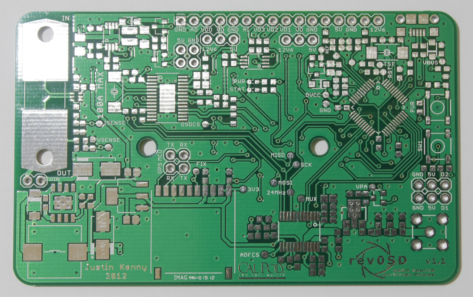
Top of the rev0SD PCB
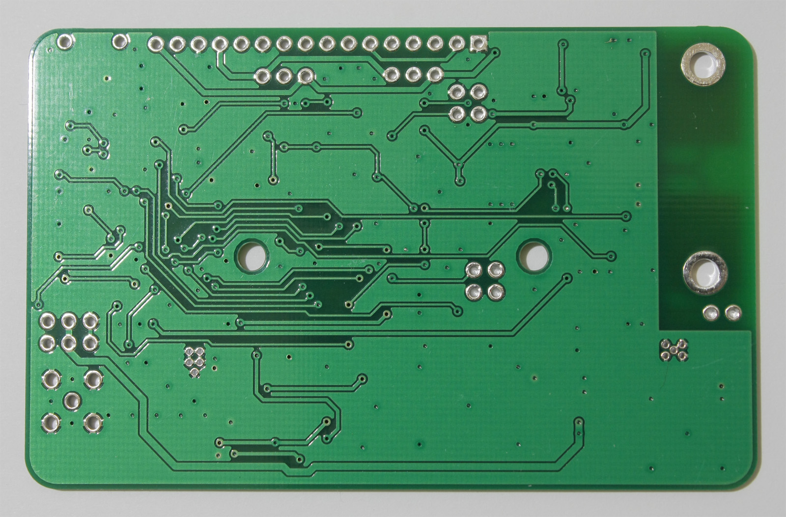
Bottom of the rev0SD PCB
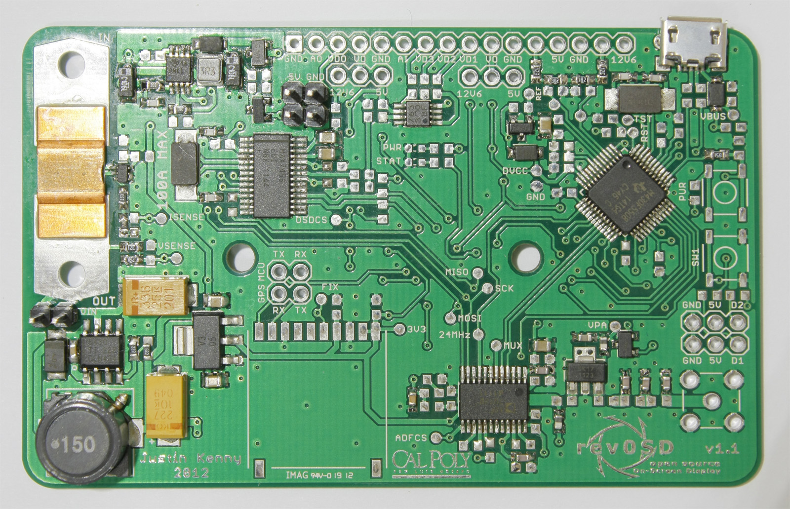
Half assembled rev0SD
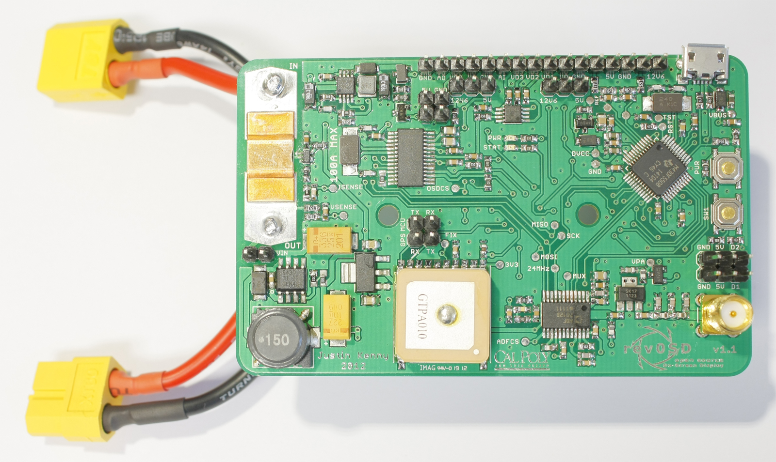
Completed rev0SD with XT-60 wiring harness
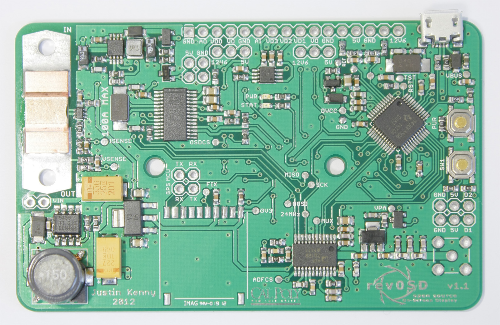
Second rev0SD, pre-reflow
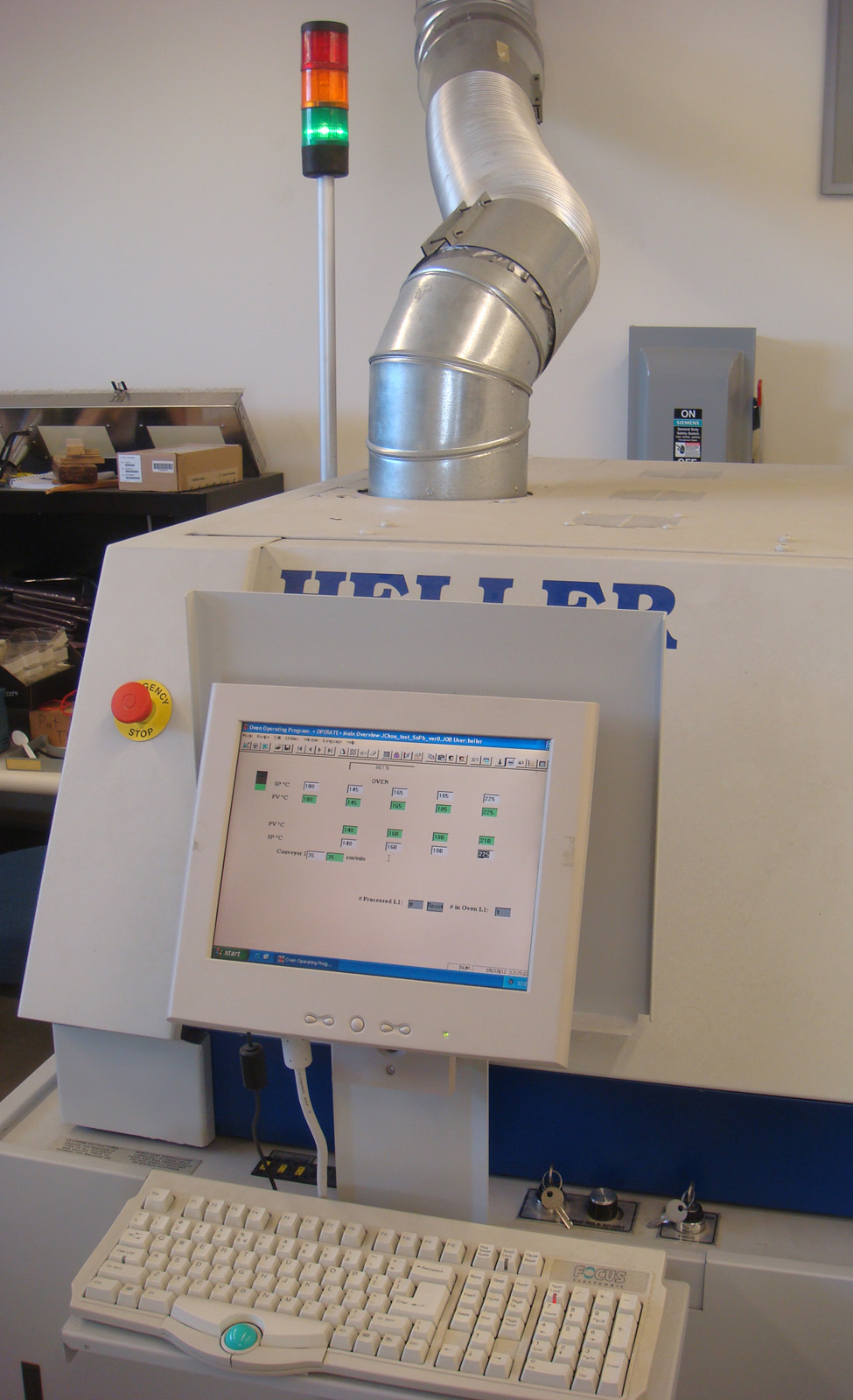
Heller reflow oven, showing solder profile
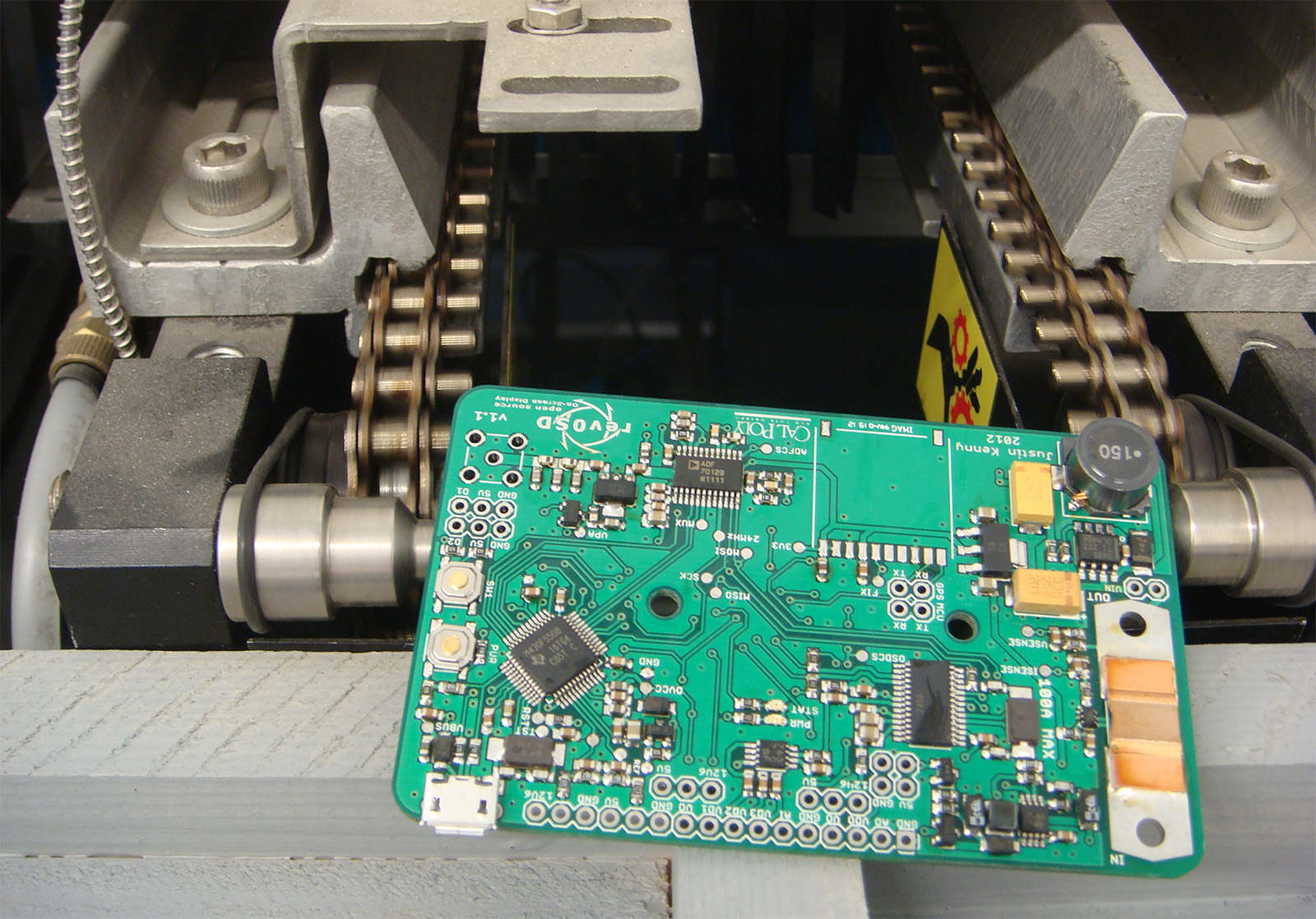
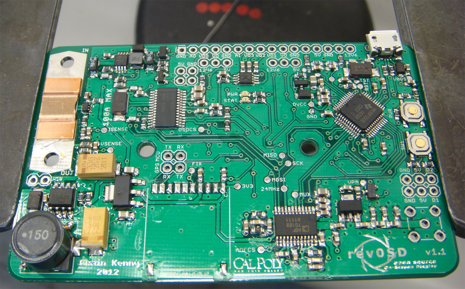
Second rev0SD, fresh out of the reflow oven
Second rev0SD, after correcting bridged components at ISense, a sideways component below the MCU, and fixing a solder joint on the 15uH power inductor


